
Cooling and accelerating vacuum carburizing method

A vacuum carburizing and speed-up technology, which is applied in coating, metal material coating process, solid-state diffusion coating, etc., can solve the problems of high carburizing temperature, uneven carburizing layer structure, high energy consumption, etc.

Active Publication Date: 2019-07-23
HARBIN ENG UNIV
View PDF4 Cites 10 Cited by
  • Summary
  • Abstract
  • Description
  • Claims
  • Application Information

AI Technical Summary

Problems solved by technology

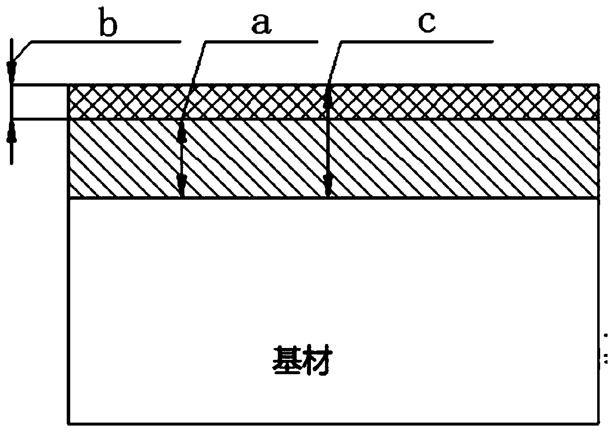
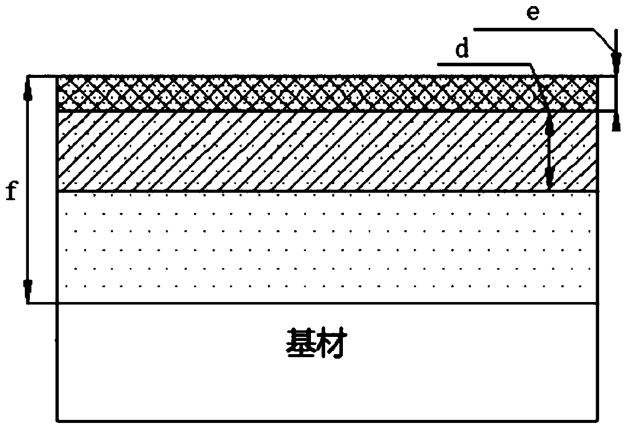
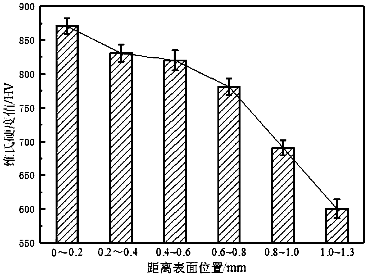
[0004] The purpose of the present invention is to solve the problems existing in the existing vacuum carburizing technology, such as high carburizing temperature, uneven carburizing layer structure, long carburizing cycle, high energy consumption, etc., and provide a method for reducing carburizing temperature and improving vacuum carburizing efficiency. And a composite surface strengthening method that uses supersonic particle bombardment technology to bombard rare earth oxide-hard ceramic mixed powder on the surface of the sample, forms a nano-rare earth modified layer on the surface of the substrate, and then performs vacuum carburizing to improve the quality of the infiltration layer.

Method used


Image

  • Cooling and accelerating vacuum carburizing method
  • Cooling and accelerating vacuum carburizing method
  • Cooling and accelerating vacuum carburizing method

Examples


specific Embodiment approach 1

[0020] Specific implementation mode one: the vacuum carburizing treatment method of cooling and increasing speed in this implementation mode is implemented according to the following steps:

[0021] 1. Base material preparation: Surface polishing and cleaning treatment are carried out on the base material in turn to obtain the cleaned base material;

[0022] 2. Compound pretreatment:

[0023] a. Mixing powder: using a ball mill to mix the rare earth oxide powder and the hard ceramic powder to obtain a mixed powder, the content of the rare earth oxide in the mixed powder is 5wt% to 20wt%;

[0024] b. Supersonic particle bombardment: the mixed powder is loaded into the supersonic particle bombardment equipment, and the cleaned substrate is placed under the gun head of the supersonic particle bombardment equipment for supersonic particle bombardment treatment, and the mixed powder is controlled during the supersonic particle bombardment process The vertical spraying distance is ...

specific Embodiment approach 2

[0028] Embodiment 2: This embodiment differs from Embodiment 1 in that the base material in step 2 is low-carbon steel (carbon content<0.25%).

[0029] The low-carbon steel described in this embodiment can be 17CrNiMo6, 18Cr2Ni4WA, 12Cr2Ni4A and the like.

specific Embodiment approach 3

[0030] Specific embodiment three: the difference between this embodiment and specific embodiment one or two is that the rare earth oxide described in step two is La 2 o 3 or CeO 2 .


PUM

PropertyMeasurementUnit
Particle sizeaaaaaaaaaa

Abstract

The invention discloses a cooling and accelerating vacuum carburizing method, and belongs to the field of heat treatment and surface engineering. The method aims to solve the problems of high carburizing temperature, long carburizing period and the like in an existing vacuum carburizing technology. The cooling and accelerating vacuum carburizing treatment method comprises the following steps of firstly, sequentially carrying out surface polishing and cleaning treatment on a substrate; secondly, mixing rare earth oxide powder with hard ceramic powder to obtain mixed powder, arranging the substrate below a gun head of supersonic particle bombardment equipment, performing supersonic particle bombardment treatment on the mixed powder, and controlling the spraying speed to be 300-1200m / s to obtain a substrate with a nanometer-rare earth modified layer; third, putting the substrate with the nanometer-rare earth modified layer into a vacuum carburizing furnace, vacuumizing in the furnace, andheating to a carburizing temperature to carry out vacuum carburizing treatment. Compared with common vacuum carburization, the composite strengthening technology adopted by the invention can reduce the carburization temperature, improve the vacuum carburization efficiency, shorten the carburization period and improve the surface hardness of a carburized layer.

Description

technical field [0001] The invention belongs to the field of heat treatment and surface engineering, and specifically relates to a nano-rare earth modified layer prepared on the surface of a material by using supersonic particle bombardment technology, so as to reduce the carburizing temperature, improve the toughness of carburizing workpieces, increase the carburizing speed and improve the quality of the carburizing layer Methods. Background technique [0002] Carburizing is the main heat treatment process to improve the comprehensive performance of mechanical parts such as gears and bearings. It changes the surface phase structure of metal materials through the infiltration of carbon atoms, so that the workpiece can achieve high surface hardness, high wear resistance and fatigue strength. It has become an ocean Necessary process before the service of metal workpieces in the fields of ships, wind power, metallurgical mines, aerospace and other fields. However, the traditio...

Claims


Application Information

Patent Timeline
IPC IPC(8): C23C8/20C23C8/02C23C8/22
CPCC23C8/02C23C8/20C23C8/22
Inventor 崔秀芳宋圣强金国董美伶刘二宝杨雨云刘金娜
Owner HARBIN ENG UNIV
Learn More