Device and method for reducing evaporation rate of liquid hydrogen storage tank by using liquid nitrogen cooling capacity
A liquid nitrogen storage tank, evaporation rate technology, applied in the direction of fixed capacity gas storage tank, container discharge method, container filling method, etc., can solve the problem of reducing the evaporation rate of liquid hydrogen storage tank, high evaporation rate of liquid hydrogen storage tank, cost and poor use efficiency to achieve the effect of reducing natural evaporation rate, reducing heat transfer temperature and high use efficiency
- Summary
- Abstract
- Description
- Claims
- Application Information
AI Technical Summary
Problems solved by technology
Method used
Image
Examples
Embodiment 1
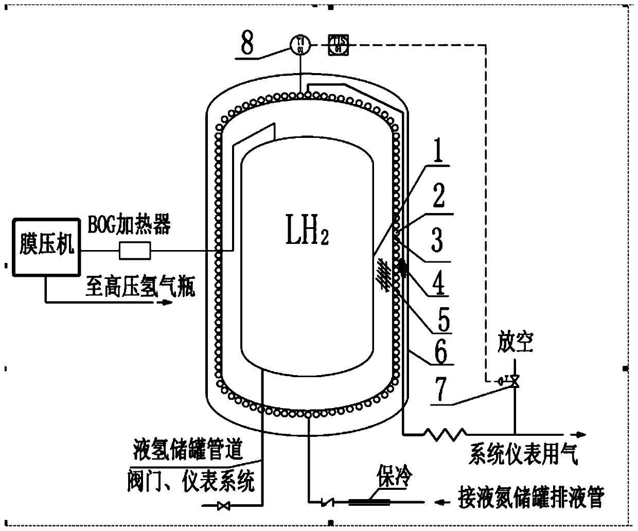
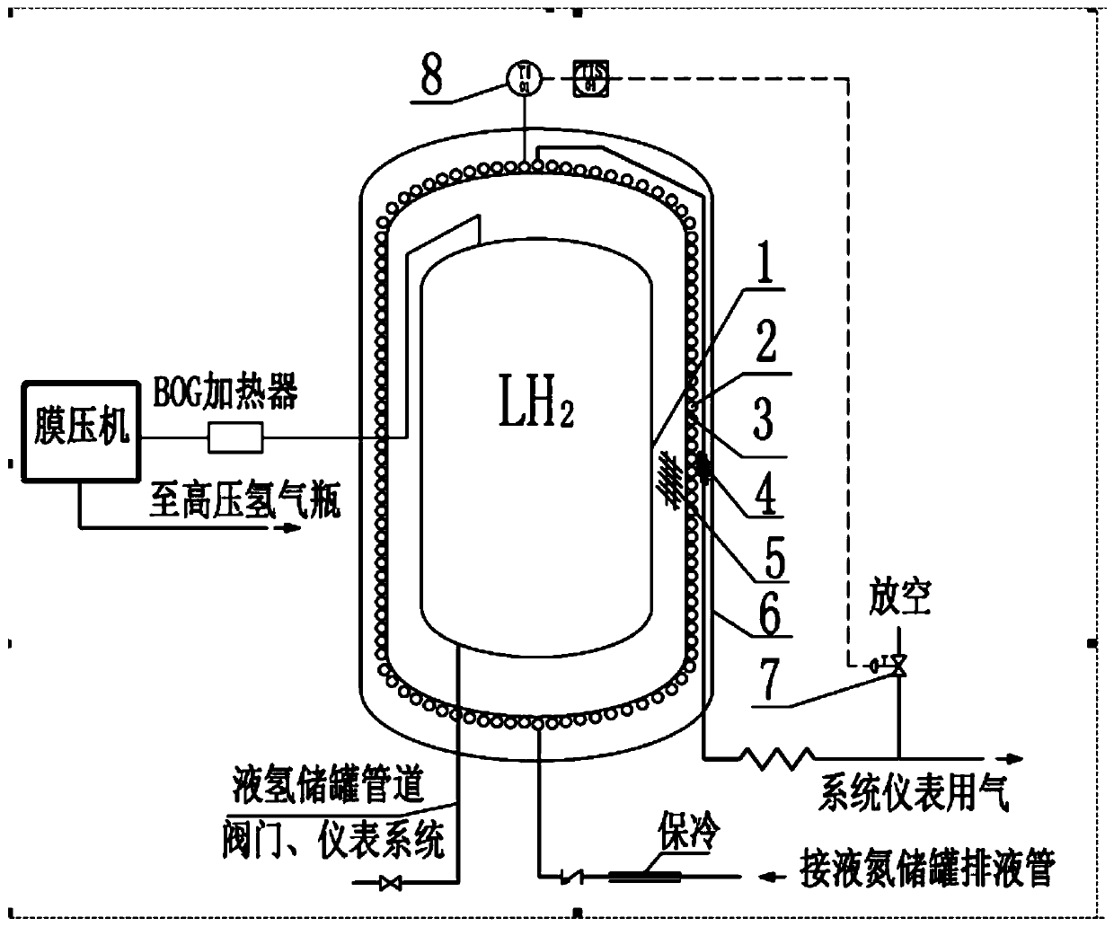
[0051] like figure 1 As shown, the device and method for reducing the evaporation rate of a liquid hydrogen storage tank by utilizing the cooling capacity of liquid nitrogen in the present invention include a liquid hydrogen storage tank, a liquid nitrogen storage tank, and instrument gas, wherein the liquid hydrogen storage tank includes a liquid hydrogen storage tank inner tank 1 and the outer tank 3 of the liquid hydrogen storage tank, a high-vacuum multi-layer insulation layer 5 is arranged between the inner tank 1 of the liquid hydrogen storage tank and the outer tank 3 of the liquid hydrogen storage tank, and the gas for the liquid nitrogen storage tank and the instrument passes through the liquid nitrogen discharge pipe connection, the outer wall of the outer tank 3 of the liquid hydrogen storage tank is coiled and connected with a liquid nitrogen discharge pipe 2 from top to bottom, and the two ends of the liquid nitrogen discharge pipe 2 are connected with the instrume...
Embodiment 2
[0056] The method for reducing the evaporation rate of a liquid hydrogen storage tank by utilizing the cooling capacity of liquid nitrogen comprises the following steps:
[0057] (1) The outer wall of the outer tank 3 of the liquid hydrogen storage tank is coiled and connected with a liquid nitrogen discharge pipe 2 from top to bottom. The liquid nitrogen in the storage tank flows into the liquid nitrogen discharge pipe 2 through the liquid nitrogen discharge pipe, and the liquid nitrogen in the liquid nitrogen discharge pipe 2 keeps the temperature of the outer tank 3 of the liquid hydrogen storage tank below -150°C;
[0058] (2) The liquid nitrogen is exchanged at the outer tank 3 of the liquid hydrogen storage tank through the liquid nitrogen exhaust pipe 2, and the vaporized liquid nitrogen is discharged through the instrument gas for use.
[0059] The regulating valve 7 arranged between the liquid nitrogen exhaust pipe 2 and the instrument gas is used to control the disch...
Embodiment 3
[0062] On the basis of Example 2, a membrane press is connected to tank 1 of the liquid hydrogen storage tank, and the membrane press recovers the evaporated hydrogen at tank 1 of the liquid hydrogen storage tank and presses it into a high-pressure hydrogen cylinder.
[0063] For the liquid hydrogen storage tank, no matter what technical measures are taken, its heat conduction and heat radiation always exist more or less, and the natural evaporation of liquid hydrogen will also be generated more or less continuously. The pressure of the liquid hydrogen storage tank With the continuous natural evaporation of liquid hydrogen, it will gradually increase. In order to ensure the safe and reliable operation of the liquid hydrogen storage tank, when the pressure of the liquid hydrogen storage tank reaches the set discharge pressure, it will be discharged through the gas phase (BOG) of the storage tank. According to the different usage occasions of the liquid hydrogen storage tank, th...
PUM
 Abstract
Description
Claims
Application Information
 - R&D
- Intellectual Property
- Life Sciences
- Materials
- Tech Scout
- Unparalleled Data Quality
- Higher Quality Content
- 60% Fewer Hallucinations
Browse by: Latest US Patents, China's latest patents, Technical Efficacy Thesaurus, Application Domain, Technology Topic, Popular Technical Reports.
© 2025 PatSnap. All rights reserved.Legal|Privacy policy|Modern Slavery Act Transparency Statement|Sitemap|About US| Contact US: help@patsnap.com


