Electric vehicle NVH optimization-based driving control method

A technology for electric vehicles and controllers, which is used in motor generator control, AC motor control, electronic commutation motor control, etc.

Active Publication Date: 2019-07-23
HANGZHOU DIANZI UNIV
2 Cites 2 Cited by

AI-Extracted Technical Summary

Problems solved by technology

The optimization of PMSM cogging torque can be done by optimizing the motor stator cogging. The opt...

Method used

A kind of control method based on optimizing electric vehicle NVH performance, its control block diagram as shown in Figure 1; By carrying out optimization process to traditional control strategy, the rule of fuzzy control is introduced in speed loop PI controller, its schematic diagram As shown in Figure 2, it has better speed regulation performance and better anti-disturbance performance; and the concept of predictive control is introduced into the current loop, and the dead zone compensation is introduced into...

Abstract

The invention discloses an electric vehicle NVH optimization-based driving control method. A new controller is designed for an input and an output of an electric vehicle driving control system, a fuzzy control idea is introduced to a speed loop controller, the robustness and more rapid speed response of a speed ring are improved, a forecast control idea is introduced to a current loop controller,a new speed forecast controller is designed, and the dynamic performance and the steady performance of the electric vehicle driving control system are improved. On the basis, dead zone error voltage compensation is performed on an output voltage of a forecast controller, an input voltage of an inverter is compensated at a current loop, the unfavorable influence of a dead zone effect on an output voltage is improved, so that the driving control system obtains more rapid current dynamic response, better steady control accuracy and higher interference resistance, torque fluctuation is prevented by voltage dead zone compensation, and an electric vehicle obtains better NVH performance and has better application value.

Application Domain

Electronic commutation motor controlAC motor control +5

Technology Topic

Power inverterElectric vehicle +9

Image

  • Electric vehicle NVH optimization-based driving control method
  • Electric vehicle NVH optimization-based driving control method
  • Electric vehicle NVH optimization-based driving control method

Examples

  • Experimental program(1)

Example Embodiment

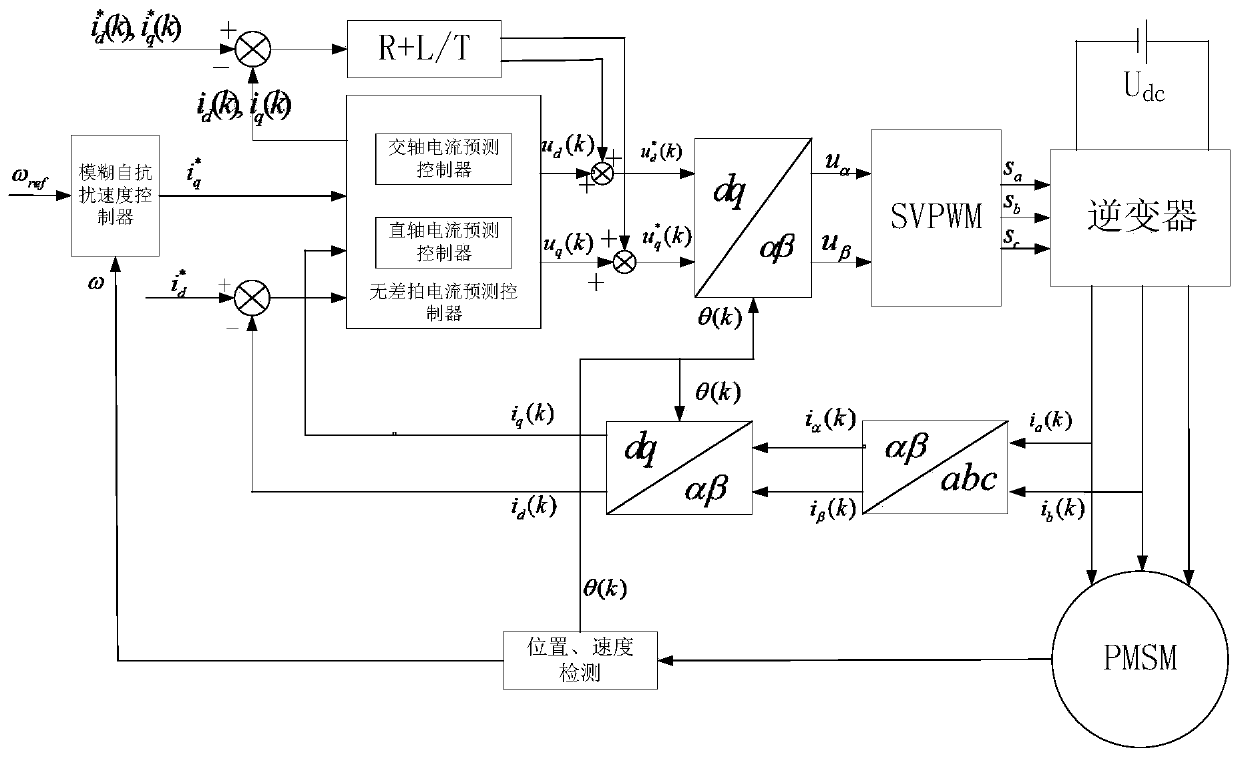
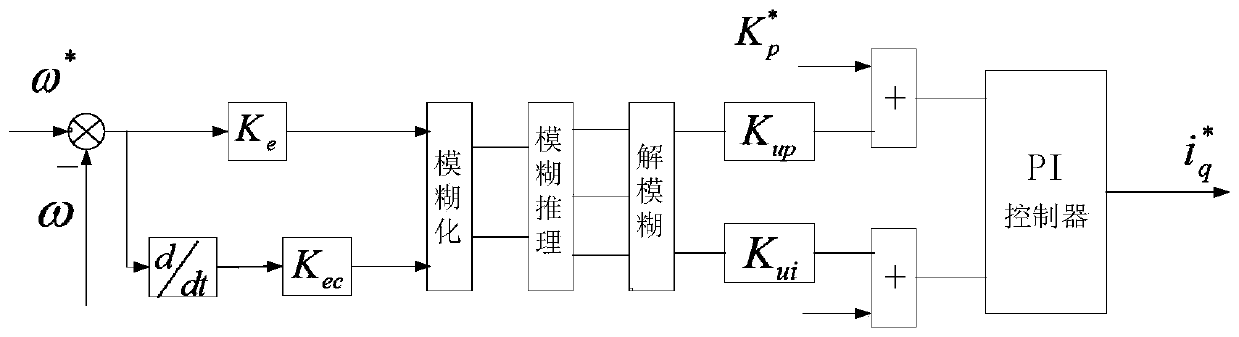
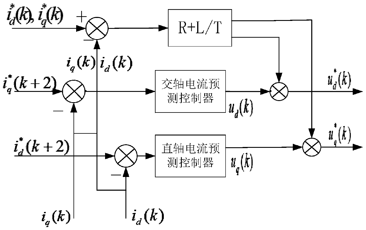
[0046] A control method based on optimizing the NVH performance of electric vehicles, the control block diagram is as follows figure 1 shown; by optimizing the traditional control strategy, the rules of fuzzy control are introduced into the speed loop PI controller, the schematic diagram is shown in the figure. figure 2 As shown in the figure, better speed regulation performance and better anti-disturbance performance; the concept of predictive control is introduced into the current loop, and dead zone compensation is introduced into the new type of predictive current controller, as shown in the schematic diagram. image 3 As shown, by compensating the voltage, a better current characteristic is obtained, and then the torque ripple is suppressed, and the NVH of the electric vehicle is optimized;
[0047] Now in conjunction with the accompanying drawings, the present invention is described in detail as follows:
[0048] Step 1: According to the given speed and the actual speed obtained by the speed sensor, select the error e and the error change rate ec of the given speed and the actual speed as the input variables, and the output variable is selected as the parameter adjustment amount ΔK of the PI controller p , ΔK i;
[0049] Step 2: According to the variation range of input variables and output variables, fuzzify them; determine the language variables for fuzzification as "negative big, negative medium, negative small, zero, positive small, positive middle, positive big", with English abbreviations For "NB, NM, NS, O, PS, PM, PB";
[0050] Step 3: Introduce the error quantization factor K e and the error rate quantization factor K ec To realize the conversion of input variables from basic universe to fuzzy universe;
[0051] Step 4: Introduce the proportional factors kup and kui of the error and the error rate of change to clarify the fuzzy amount to achieve precise control;
[0052] Step 5: Select the triangular function as the membership function of the input and output, and determine ΔK considering the control performance p , ΔK i control rule table
[0053] ΔK p control rule table
[0054]
[0055] ΔK i control rule table
[0056]
[0057] Step 6: Use the center of gravity method to de-blur the obtained fuzzy output to obtain ΔK p , ΔK i The exact output value of ;
[0058] Step 7: Obtain the reference stator quadrature axis current through the speed loop controller i.e. i q [k+2]; Obtain the actual stator quadrature axis current i through the current sensor q [k];
[0059] Step 8: In the Kth sampling period, the coordinate transformation module provides the three-phase stator current ia(k), ib(k) and ic(k) provided by the current sensor and the position angle θ(k) obtained by the position sensor Perform coordinate transformation to obtain the stator direct-axis current id(k) and the stator quadrature-axis current iq(k) in the d-q coordinate system;
[0060] Step 9: Obtain the direct and quadrature axis voltages U at time K through the current prediction controller q [k], U d [k];
[0061] Step 10: The dead zone compensation module performs dead zone compensation on the obtained direct and quadrature axis voltages to obtain the compensated direct and quadrature axis voltages
[0062] Step 11: The coordinate transformation module performs coordinate transformation on the d-q axis voltage in the rotating coordinate system to obtain two voltages in the stationary coordinate system
[0063] Step 12: The SVPWM modulation module aligns the voltage commands obtained by the direct and quadrature axis current prediction controllers Perform processing to obtain on-off signals Sa[k], Sb[k], Sc[k] of the switching tubes of the inverter, and transmit them to the inverter;
[0064] Step 13: The inverter uses the control signals Sa[k], Sb[k], Sc[k] obtained by the SVPWM modulator to control the inverter to output the three-phase stator voltage of the electric vehicle drive motor, so as to realize the Optimal control of NVH performance in electric vehicles.

PUM

no PUM

Description & Claims & Application Information

We can also present the details of the Description, Claims and Application information to help users get a comprehensive understanding of the technical details of the patent, such as background art, summary of invention, brief description of drawings, description of embodiments, and other original content. On the other hand, users can also determine the specific scope of protection of the technology through the list of claims; as well as understand the changes in the life cycle of the technology with the presentation of the patent timeline. Login to view more.
Why Eureka
Try Eureka