Sealed circulating flow heat exchange and cooling system for granary and cooling method thereof

A technology of granary and heat exchange plate, applied in the fields of botanical equipment and method, fruit hanging device, gardening, etc., can solve the problems such as the inability to form a low-temperature cold core, the inability of warehousing enterprises to bear economic losses, and the reduction of grain temperature.

Pending Publication Date: 2019-07-26
HENAN BROTHER TECH DEV CO LTD
View PDF0 Cites 7 Cited by
  • Summary
  • Abstract
  • Description
  • Claims
  • Application Information

AI Technical Summary

Problems solved by technology

In order to form a cold core with a lower temperature in the grain pile, it is necessary to fully ventilate the grain in winter to cool the grain. Because the northern grain depots are worried about excessive ventilation causing excessive moisture loss in the grain and are unwilling to ventilate too much, they cannot The low-temperature cold core is formed, which leads to the inability of the internal circulation temperature control technology to be fully implemented; the southern grain depot is worried that low temperature and humidity will increase the grain moisture and cause the water to rise beyond the standard and cannot be ventilated, so the role of the internal circulation temperature control technology cannot be fully utilized
[0011] The main reason why ventilation and temperature control storage technology and internal circulation temperature control technology cannot fully play their role is that the current ventilation method is an open ventilation and cooling method, which directly introduces external air into the grain pile, which also reduces the temperature of the grain during cooling. Water, too much water loss Storage enterprises cannot bear the economic loss, which makes enterprises unwilling to lower the temperature of grain to a lower temperature, which affects the safe storage of grain and also affects the maintenance of fresh quality of grain

Method used


Image

  • Sealed circulating flow heat exchange and cooling system for granary and cooling method thereof
  • Sealed circulating flow heat exchange and cooling system for granary and cooling method thereof
  • Sealed circulating flow heat exchange and cooling system for granary and cooling method thereof

Examples


Embodiment 1

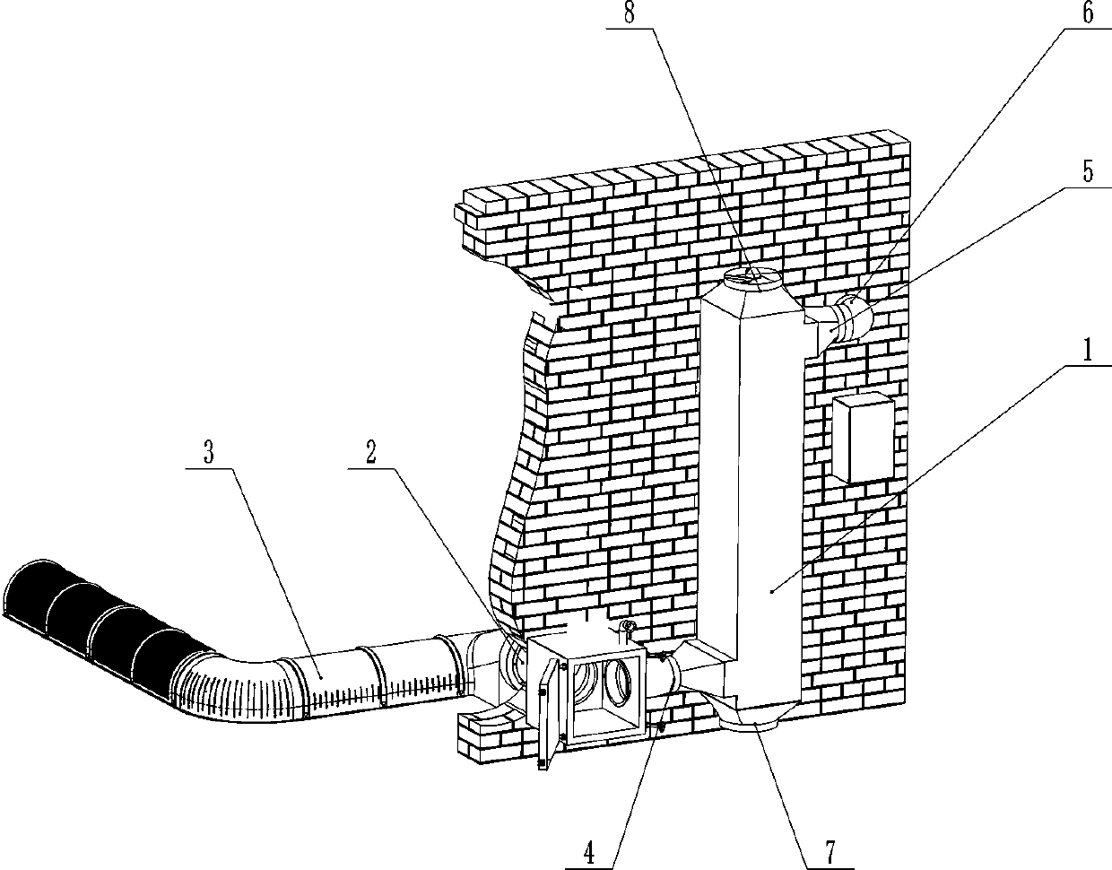
[0039] Such as figure 1 As shown, a granary closed loop heat exchange and cooling system includes a heat exchanger 1 installed on the outer wall of the granary, a ventilator 2 and an internal ventilation pipe network of the granary; the internal ventilation pipe network of the granary includes a ventilation cage 3, and the The outlet of the ventilation cage 3 is in sealing communication with the fan, and the fan is in sealing communication with the hot air inlet 4 of the heat exchanger 1 .

[0040] The hot air outlet 5 of the heat exchanger is connected to the interior of the granary through the hot air outlet connecting pipe 6 to form a closed circulation channel for hot air in the granary isolated from the outside world; the cold air inlet 7 and the cold air outlet 8 of the heat exchanger 1 are respectively It communicates with the atmosphere to form an atmospheric cold air passage isolated from the closed circulation passage of the granary hot air.

[0041] This embodiment...

Embodiment 2

[0051] In order to solve the cooling problem of controlled atmosphere storage in winter without changing the concentration of nitrogen or carbon dioxide gas in controlled atmosphere, it can be realized by the closed circulation heat exchange and cooling system of this granary. After the grain is stored, several grain surface ventilation pipes are laid at 10cm-20cm below the top grain surface. The length of the grain surface ventilation pipes is close to the span of the granary. Form an air inlet, which is connected to the hot air outlet of the heat exchanger through the hot air outlet connecting pipe, cover the grain surface with a plastic film to seal the grain surface, and finally replace the air in the granary with nitrogen or carbon dioxide, and seal it when the concentration meets the requirements Grain silos and grain piles realize controlled atmosphere storage.

[0052] In winter, to cool down the grain stored under controlled atmosphere, the nitrogen or carbon dioxide ...

Embodiment 3

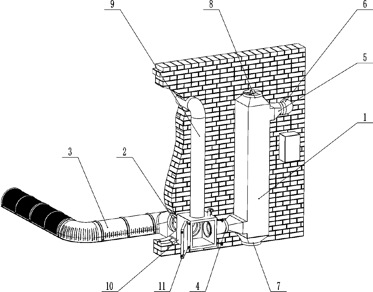
[0055] Such as figure 2 As shown, the difference between this embodiment and Embodiments 1 and 2 is that the internal ventilation pipe network of the granary also includes a thermal insulation circulation pipe 9 and a thermal insulation closed box 10, and the thermal insulation closed box 10 has three interfaces and an opening and closing The airtight box body of the box door 11, the outlet of the ventilator, the inlet of the heat preservation circulation pipe 9 and the hot air inlet 4 of the heat exchanger 1 are respectively sealed and connected to the three interfaces of the heat preservation airtight box 10 , wherein the two interfaces connected with the air inlet of the thermal insulation circulation pipe and the hot air inlet of the heat exchanger are equipped with sealing plugs, and the outlet of the thermal insulation circulation pipe 9 is used to communicate with the inside of the granary.

[0056] The structure added in this embodiment is to utilize the grain cooled ...


PUM


Abstract

The invention provides a sealed circulating flow heat exchange and cooling system for a granary and a cooling method thereof. The sealed circulating flow heat exchange and cooling system comprises a heat exchanger, a ventilation machine and an in-granary ventilation pipe net, wherein a hot air channel in the heat exchanger, the in-granary ventilation pipe net and the ventilation machine jointly form an in-granary hot air closed circulation channel for isolating air outside the granary; a cold air channel in the heat exchanger and a strong convection fan form an open channel communicated with the atmosphere. When the temperature difference between the temperature of grains and the atmosphere reaches a pre-set startup value, the system is started up; in-granary hot air is internally circulated in the hot air sealed circulation channel through the ventilation machine, and cold air in the atmosphere is sucked by the strong convection fan from a cold air inlet of the heat exchanger and thenis exhausted from a cold air outlet through the cold air channel. The cold air of the atmosphere and the in-granary hot air are subjected to heat exchange in the heat exchanger and the in-granary hotair is cooled and then is returned back to the granary to realize the aim of cooling. When the system provided by the invention is used for cooling the granary, the system is not influenced by atmospheric humidity and the moisture of the grains is not influenced, so that the disadvantages of open type ventilation are overcome.

Description

technical field [0001] The invention belongs to the field of grain ventilation and storage, and in particular relates to a granary airtight circulation heat exchange cooling system and a cooling method thereof. Background technique [0002] Grain ventilated storage is the mainstream technology of grain storage at present, which provides reliable technical support for safe grain storage. The basic principle is that before the grain enters the warehouse, a ventilation pipe with densely distributed small ventilation holes (later referred to as a ventilation cage) is laid in the granary, or a ventilation trough is installed on the floor in the warehouse, and a ventilation pipe with densely distributed small ventilation holes is laid on the ground trough. The cover plate (hereinafter referred to as the trough cover plate) connects the ventilation duct or the ventilation slot with the ventilation opening set on the wall of the granary, and uses a blower to blow air into the granar...

Claims


Application Information

Patent Timeline
IPC IPC(8): A01F25/16A01F25/22
CPCA01F25/16A01F25/22
Inventor 卢振江卢兆焓
Owner HENAN BROTHER TECH DEV CO LTD
Why Eureka
Try Eureka