Eureka AIR delivers breakthrough ideas for toughest innovation challenges, trusted by R&D personnel around the world.

Visual servo laser positioning system and method of picking robot

A picking robot and visual servo technology, which is applied in the field of visual servo laser positioning system, can solve the problems of low scanning resolution, difficulty in accurately obtaining the spatial position of objects, and inability to obtain accurate information of objects, so as to reduce costs, improve measurement accuracy, The effect of reducing the amount of data processing

Active Publication Date: 2019-07-30
北京禾泽方圆智能科技有限公司
View PDF11 Cites 9 Cited by
  • Summary
  • Abstract
  • Description
  • Claims
  • Application Information

AI Technical Summary

Problems solved by technology

Among them, based on the binocular vision of the detection point matching principle, the target is positioned by the method of triangulation measurement. In this method, the corner point data is too sparse or too dense, and the requirements for the corner point matching algorithm are very high. Accurate acquisition The spatial position of the object is more difficult; the surface scanning laser radar is not suitable for the spatial positioning requirements of small objects due to its low scanning resolution; both the structured light camera and the TOF camera measure by actively emitting auxiliary light sources, and the structured light The coded infrared light emitted by the camera is positioned by identifying the code change of the infrared light projected on the surface of the object, while the TOF camera emits infrared light with certain information, which is determined by calculating the time it takes for the light to reflect on the surface of the object. Realize the acquisition of the distance of the object, but these two methods are easily interfered by the sun's rays in the outdoor environment due to the active luminescence, so that the accurate information of the object cannot be obtained

Method used


Image

  • Visual servo laser positioning system and method of picking robot
  • Visual servo laser positioning system and method of picking robot
  • Visual servo laser positioning system and method of picking robot

Examples


Embodiment 1

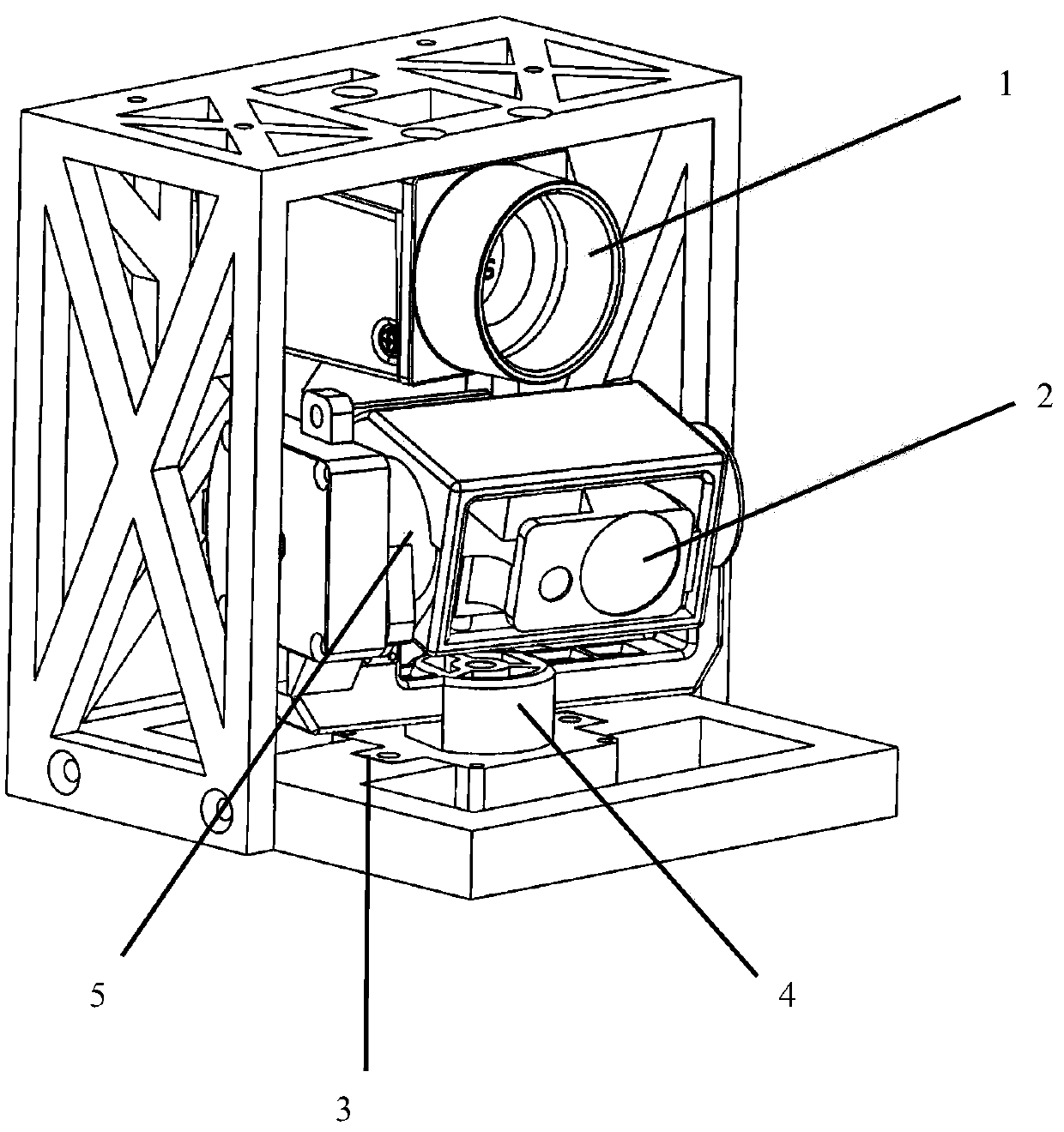
[0054] like figure 1 As shown, Embodiment 1 of the present invention provides a visual servo laser positioning system for a picking robot. After the system positions the picked objects, it needs to cooperate with an external grabbing device for picking operations. The positioning system specifically includes a controller (not shown in the figure, a single-chip microcomputer can be used, or a computer can be directly used to run the control software), a monocular camera 1, and a laser ranging module 2 arranged below the monocular camera 1. 1 and the laser ranging module 2 are connected to the controller by communication; the laser ranging module 2 is installed on the two-dimensional pan-tilt 3, and the two-dimensional pan-tilt 3 includes an X-axis servo motor 4 that controls the horizontal rotation of the laser ranging module 2, and Control the Y-axis servo motor 5 that the laser ranging module 2 rotates vertically;

[0055] The controller adjusts and trains the existing deep ...

Embodiment 2

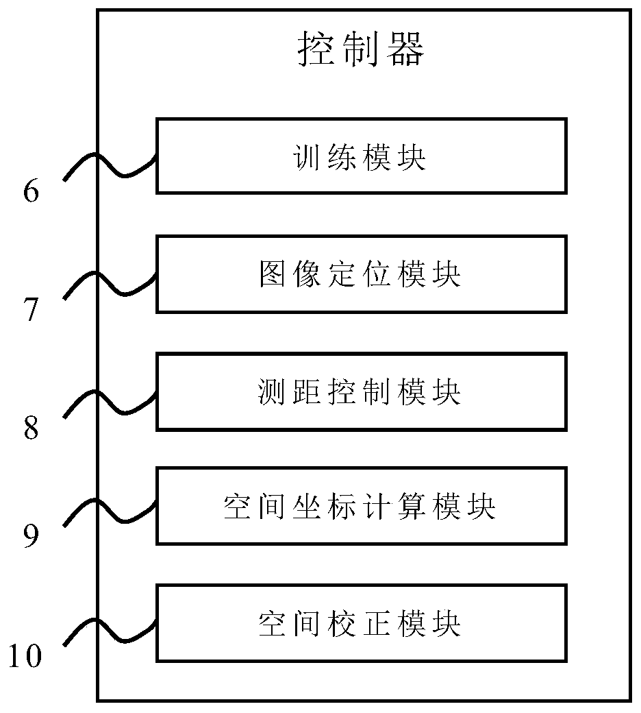
[0059] like figure 2 As shown, present embodiment 2 provides a kind of visual servo laser positioning system of picking robot on the basis of embodiment 1, and this embodiment 2 further defines that the controller includes the following parts:

[0060] The training module 6 is used to carry out training, verification and testing as a sample set with a plurality of sample images taken by the monocular camera 1 in the picking environment, to obtain a well-trained deep learning network algorithm;

[0061] The training method can use saturation, edge features, feature classification and other methods to learn and train the sample images in order to accurately identify the target object from the picking environment;

[0062] The image positioning module 7 is used to locate the target object in the two-dimensional image of the picking environment obtained by the monocular camera 1, and obtain the spatial position coordinates of the target object relative to the monocular camera 1, ...

Embodiment 3

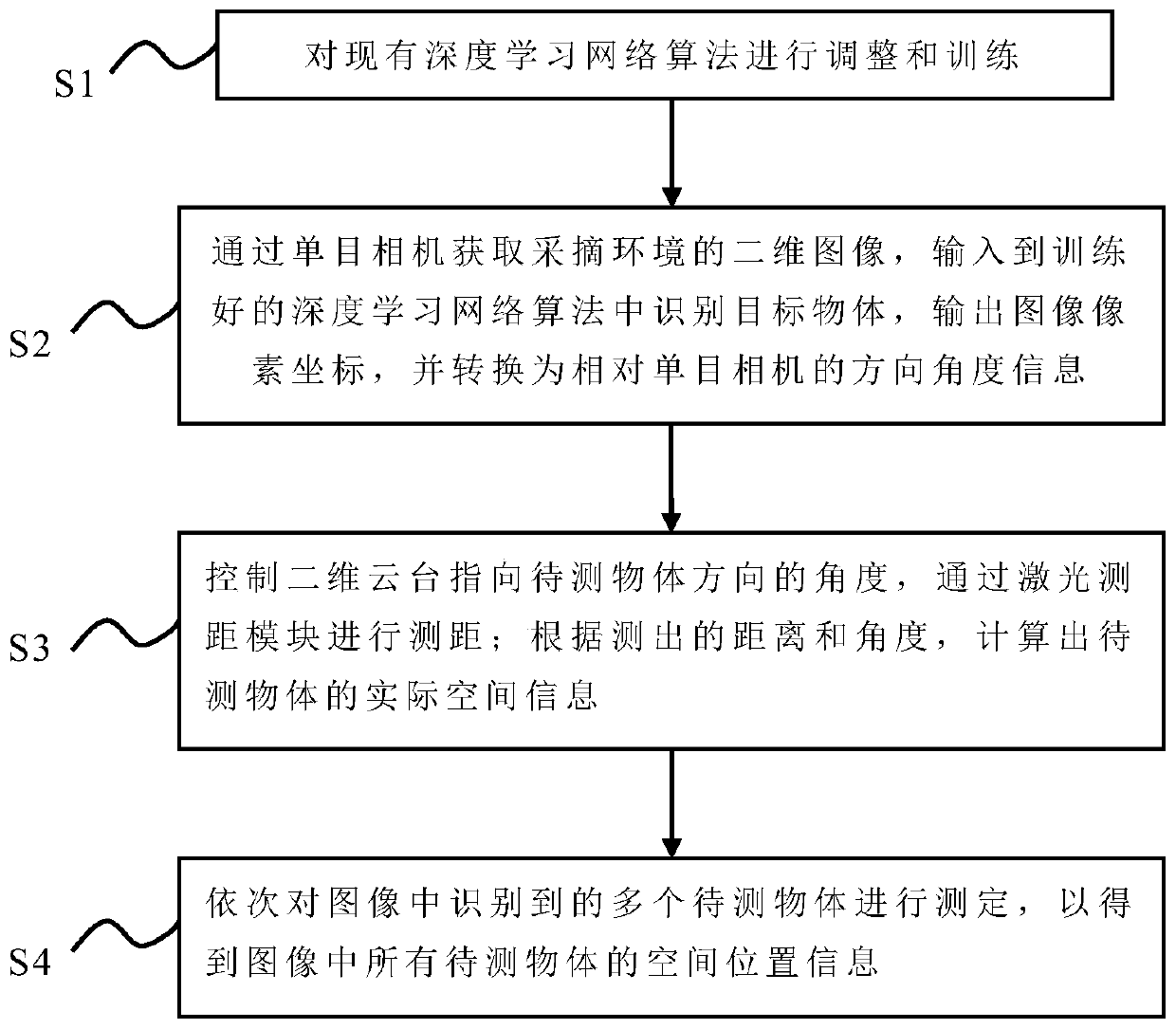
[0068] like image 3 As shown, the present embodiment 3 provides the visual servo laser positioning method of the picking robot applying the above-mentioned system, which specifically includes the following steps:

[0069] S1: Adjust and train existing deep learning network algorithms;

[0070] S2: Obtain the two-dimensional image of the picking environment through the monocular camera 1, input it into the trained deep learning network algorithm to identify the target object, and output the image pixel coordinates of multiple target objects; convert the coordinates of the target object into the target object relative The direction and angle information of the monocular camera 1;

[0071] S3: control the angle at which the two-dimensional pan-tilt 3 points to the direction of the object to be measured, and perform distance measurement by the laser ranging module 2; calculate the actual spatial information of the object to be measured according to the measured distance and angl...


PUM


Abstract

The invention provides a visual servo laser positioning system of a picking robot and a corresponding method. A controller trains an existing depth learning network algorithm, a monocular camera acquires a two-dimensional image of a picking environment, inputs the two-dimensional image into the algorithm to identify a target object and outputs direction angle information relative to the monocularcamera, a two-dimensional holder points to the direction of the object to be detected, and a laser ranging module is used for ranging; and finally, the controller calculates the actual spatial information of the object to be detected according to the measurement result. According to the system and the method, the advantages of depth vision and laser ranging are combined, monocular depth vision andthe single-point laser ranging module with a two-dimensional servo structure are adopted to measure the spatial positions of a limited number of targets in an outdoor environment, so that the required specific target objects are spatially positioned in an unstructured environment, the measurement precision can be effectively improved, the data processing amount is reduced, the cost is reduced, and the system and the method are suitable for picking various fruits and vegetables in indoor and outdoor environments.

Description

technical field [0001] The invention belongs to the field of object recognition and positioning, in particular to a visual servo laser positioning system and method for a picking robot. Background technique [0002] With the gradual improvement of the modernization of agricultural production, more and more traditional human labor can be replaced by machines. Picking is the most time-consuming, labor-intensive, and seasonal link in the agricultural production chain. Therefore, improving the automation of picking will greatly improve the efficiency of agricultural production. Automatic picking will inevitably involve the identification and positioning of harvestable parts such as fruits on crops. The existing methods for spatial positioning of objects include: binocular vision, laser radar, structured light camera and TOF camera. Among them, based on the binocular vision of the detection point matching principle, the target is positioned by the method of triangulation measure...

Claims


Application Information

Patent Timeline
IPC IPC(8): B25J9/16B25J13/08B25J19/02G01B11/02G01B11/26G06K9/00
CPCB25J9/1697B25J13/087B25J19/023G01B11/026G01B11/26G06V20/10
Inventor 张潞陈俊文王康
Owner 北京禾泽方圆智能科技有限公司
Why Eureka
Eureka Blog
Learn More