
Motor train unit pump box unit device and manufacturing method thereof

A technology of a unit device and a manufacturing method, which is applied to pump devices, pump components, pump control and other directions, can solve the problems of easy freezing of water remaining in the piping system, no automatic emptying function, and high pressure of the piping system, so as to avoid failure to operate normally. Use, improve the working efficiency and stability of pump water, and prevent the effect of rupture

Inactive Publication Date: 2019-07-30
青岛四机宏达工贸有限公司
View PDF0 Cites 3 Cited by
  • Summary
  • Abstract
  • Description
  • Claims
  • Application Information

AI Technical Summary

Problems solved by technology

[0003] However, the pump box unit devices currently on the market have no pressure protection function, which may easily cause leakage due to excessive pressure on the piping system; without automatic emptying function, the water in the piping system may freeze easily and cause the piping system to rupture

Method used


Image

  • Motor train unit pump box unit device and manufacturing method thereof
  • Motor train unit pump box unit device and manufacturing method thereof
  • Motor train unit pump box unit device and manufacturing method thereof

Examples


Embodiment 1

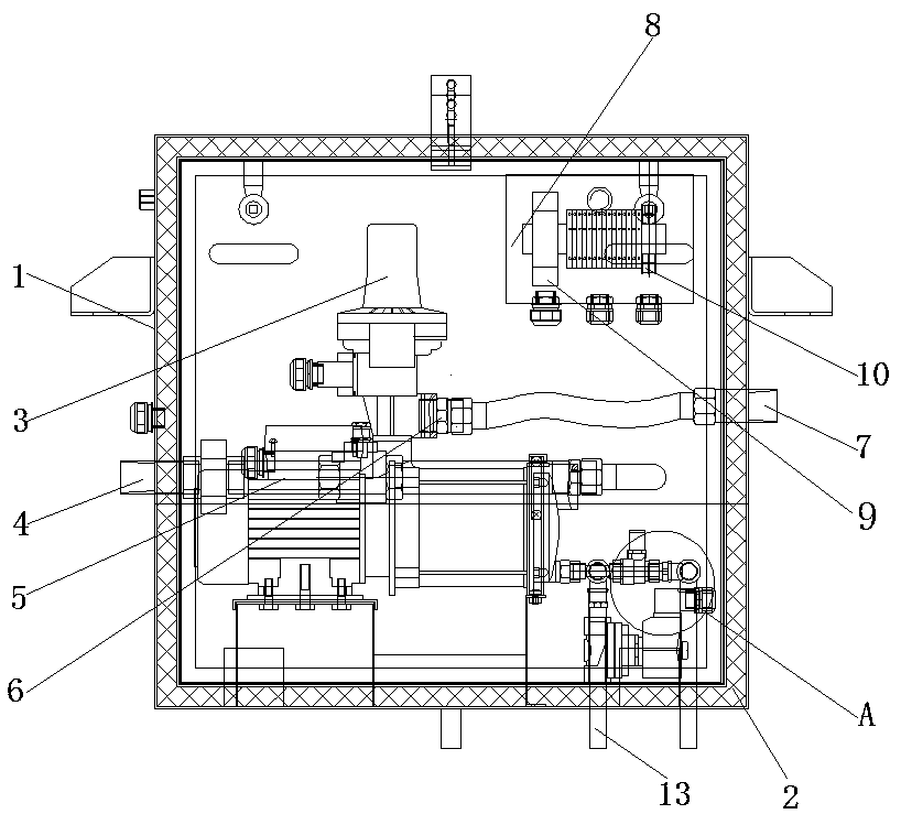
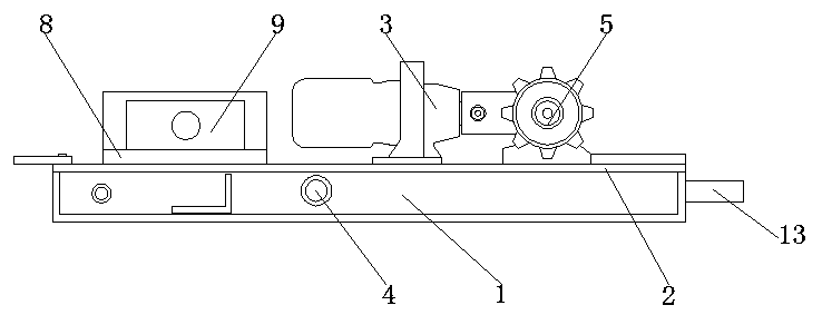
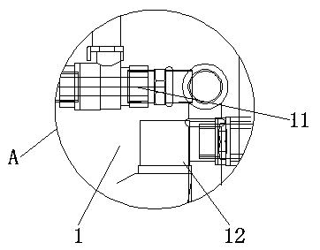
[0048] see Figure 1-3 , in an embodiment of the present invention, a pump box unit device for an EMU, including a box body 1 and a water pump 6 installed in the box body 1, a water inlet pipe 4 and a water outlet pipe 7 are installed on the box body 1, and the water inlet pipe 4 It is arranged on one side of the box body 1, and the other side of the box body 1 is provided with a water outlet pipe 7;

[0049] The inner wall of the box 1 is provided with an insulating material 2; through the use of the insulating material 2, the components inside the box 1 can be isolated and protected to prevent external low-temperature gas from entering the device, thereby reducing the operating time of the device. the possibility of malfunctions;

[0050] A pressure switch 3 is installed on the upper part of the water pump 6, and the pressure switch 3 is fixed on the box body 1 by screws; the pressure switch 3 makes the device have a pressure protection function, thereby improving the pumpi...

Embodiment 2

[0062] In an embodiment of the present invention, a manufacturing method based on the EMU pump box unit device described in Embodiment 1 includes the following steps:

[0063] Step 1. Paste insulation material 2 and aluminum foil inside the box 1 and the box door: the construction of the sealant should be carried out under the conditions of relative humidity 35-75% and room temperature 5°C-35°C;

[0064] Step 2. Assembling the pressure switch 3: Wrap the pipe magic rope evenly around the thread at the lower end of the pressure switch 3 for 8-12 turns, tighten the pressure switch 3 and the water pump 6, and the water outlet of the pressure switch 3 and the water inlet of the water pump 6 are on the same side;

[0065] Step 3. Assemble the drainage pipeline: evenly apply special railway sealant to the long end thread of the 3 / 8" tee and wind 3-5 turns of the pipeline magic rope, and fasten it with the water pump 6; preferably, the railway special The sealant is Loctite 577;

[...


PUM


Abstract

The invention relates to the technical field of pump box unit design, in particular to a motor train unit pump box unit device. The device comprises a box body and a water pump arranged in the box body, the inner wall of the box body is provided with a heat preservation material, the upper part of the water pump is provided with a pressure switch, the bottom of the pressure switch is connected with the water outlet pipe, a second junction box is arranged in the box body, a transmitter and a relay are arranged in the second junction box, the bottom of the water pump is connected with a manual ball valve through a tee joint, the outer side of the manual ball valve is connected with an electromagnetic valve, and the bottom of the electromagnetic valve is connected with a drain pipe. The device further discloses a manufacturing method of the motor train unit pump box unit device, according to the motor train unit pump box unit device, parts inside the box body can be isolated and protectedthrough the heat preservation material, external low-temperature gas is prevented from entering the device, the water pump and the water supply can be carried out in winter through the heat tracing device, the normal work of the drainage pipeline is effectively protected and guaranteed, and the phenomenon that the icing phenomenon occurs when the temperature is low is avoided.

Description

technical field [0001] The invention relates to the technical field of pump box unit design, in particular to a pump box unit device for an EMU and a manufacturing method thereof. Background technique [0002] With the continuous development of high-speed railways, the widespread application of high-speed trains and the continuous improvement of speed, the requirements for the function and stability of vehicle water supply systems are also getting higher and higher. The high-speed train pump box unit device works according to the signal requirements of the MIO unit on the train to meet the train's daily water supply and antifreeze drainage requirements, thereby ensuring the normal operation of the train. [0003] However, the pump box unit devices currently on the market have no pressure protection function, which may easily cause leakage of the piping system due to excessive pressure; without automatic emptying function, the water retained in the piping system is likely to ...

Claims


Application Information

Patent Timeline
Patent Type & Authority Applications(China)
IPC IPC(8): F04B23/02F04B53/16F04B53/10F04B49/06F04B49/08B61C17/02
CPCB61C17/02F04B23/021F04B49/06F04B49/08F04B53/1002F04B53/16
Inventor 矫翠华
Owner 青岛四机宏达工贸有限公司
Learn More