
Long distance ranging device based on laser frequency modulation continuous wave and dispersion compensation method

A frequency-modulated continuous wave and dispersion compensation technology, which is used in measurement devices, re-radiation of electromagnetic waves, radio wave measurement systems, etc. It can solve problems such as inability to accurately obtain distance information, no laser ranging, dispersion compensation, and resampling errors. , to achieve the effect of improving measurement efficiency and ranging accuracy, high efficiency and easy integration

Pending Publication Date: 2019-07-30
TIANJIN UNIV
View PDF7 Cites 16 Cited by
  • Summary
  • Abstract
  • Description
  • Claims
  • Application Information

AI Technical Summary

Problems solved by technology

However, as the measurement distance increases, due to the introduction of optical fiber dispersion, the dispersion mismatch between the auxiliary interference optical path and the main measurement optical path will lead to resampling errors, especially in long-distance and large-bandwidth measurement scenarios, the above errors will be very serious. If it is not eliminated, the distance information will not be obtained accurately
[0006] After searching, no public documents were found that recorded related content such as laser ranging and dispersion compensation

Method used


Image

  • Long distance ranging device based on laser frequency modulation continuous wave and dispersion compensation method
  • Long distance ranging device based on laser frequency modulation continuous wave and dispersion compensation method
  • Long distance ranging device based on laser frequency modulation continuous wave and dispersion compensation method

Examples


Embodiment

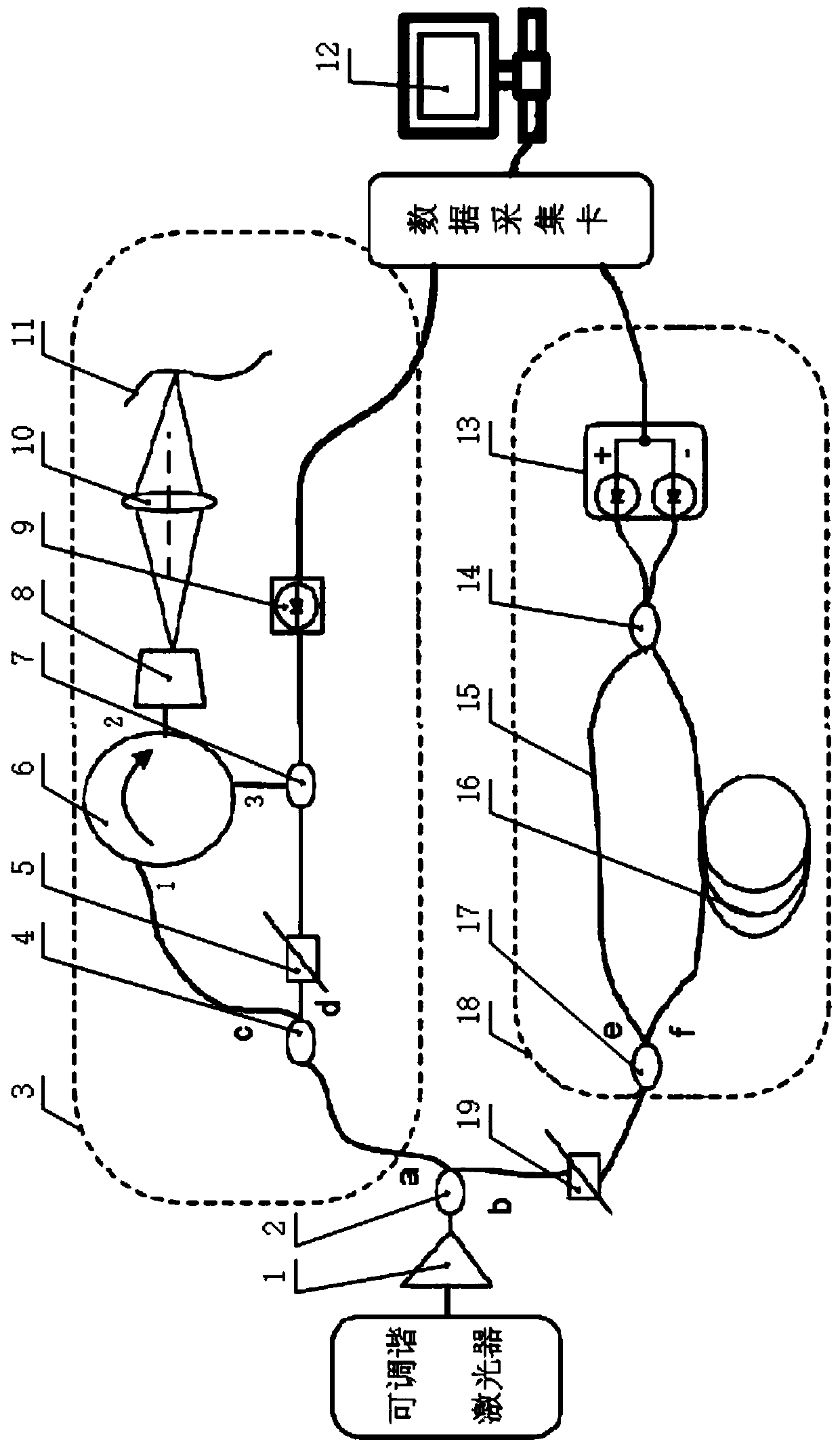
[0099] To build a long-distance measurement system with laser frequency modulation and double interference optical path, the laser is PHOENIX1400 from Luna Company in the United States, the tuning bandwidth is set to 1545nm-1555nm, and the tuning speed is set to 1000nm / s.

[0100] The delay fiber of the auxiliary interferometer is the G652 standard single-mode fiber produced by Wuhan Changfei Company, with an average refractive index of 1.467@1550nm and a length of 80.3m.

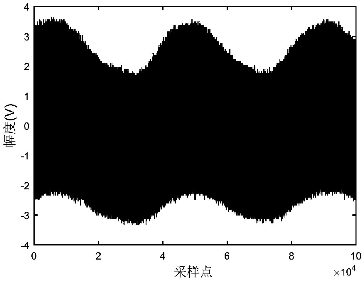
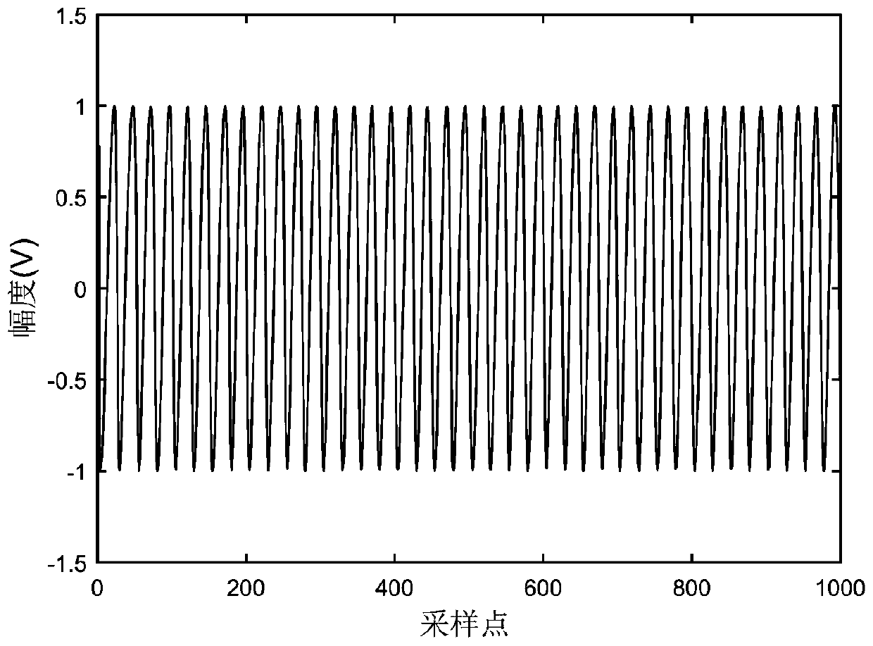
[0101] Use the zero-crossing point of the beat frequency signal of the auxiliary interference optical path to resample the main measurement interference optical path to obtain the resampled signal U res (k) if figure 2 shown;

[0102] In order to eliminate the spectral distortion caused by dispersion, the following steps are adopted:

[0103] Step 1. First, the resampled signal U containing low-frequency noise res (k) Perform Hilbert transform to construct complex signal X 0 (k);

[0104]

[0105] ...


PUM


Abstract

The invention relates to a long distance ranging device based on laser frequency modulation continuous wave, wherein a laser emitting unit is used for outputting a tunable laser, one ends of a main measuring interference optical path and an auxiliary interference optical path are respectively used for receiving the tunable laser, the other ends of the main measuring interference optical path and the auxiliary interference optical path are both connected to a data acquisition processing unit, and the data acquisition processing unit receives the two beat signals output by the main measurement interference optical path and the auxiliary interference optical path and calculates the distance spectrum information after the dispersion compensation is calculated. The long distance ranging deviceprovided by the invention can effectively eliminate the influence of the low frequency noise on the widening of the distance spectrum and can quickly perform dispersion compensation with high efficiency and very easy integration into the measurement program. By comparison, the dispersion compensation method can quickly compensate in real time to improve measurement efficiency and ranging accuracy,and is especially suitable for synthetic aperture radar, driverless measurement, medical coherence tomography, laser vibration measurement and other fields.

Description

technical field [0001] The invention belongs to the technical field of precision measurement, and relates to a long-distance ranging device and a compensation method, in particular to a laser frequency-modulated continuous wave-based long-distance ranging device and a dispersion compensation method. [0002] technical background [0003] The rapid development of industrial technology has brought more and more convenience to today's life. However, the development of industrial technology is inseparable from industrial manufacturing. With the development of the times, people's requirements for manufacturing precision and manufacturing complexity are becoming more and more stringent. It is imminent to seek a fast and high-precision in-situ measurement method. [0004] Laser frequency modulation measurement technology is also called frequency modulation laser radar technology, which has the characteristics of fast, high dynamic range and high precision, and has attracted more and...

Claims


Application Information

Patent Timeline
IPC IPC(8): G01S17/32
CPCG01S17/34
Inventor 潘浩张福民曲兴华周伦彬
Owner TIANJIN UNIV
Learn More