Photocatalytic system with photoresponse switch and self-indication property as well as preparation method and application

A photocatalytic and photoresponsive technology, applied in the field of photocatalysis, can solve the problems of different degrees of degradation of plastics, no plastic stability period, no indicator system, etc.

Active Publication Date: 2019-08-02
EAST CHINA NORMAL UNIV
View PDF3 Cites 7 Cited by
  • Summary
  • Abstract
  • Description
  • Claims
  • Application Information

AI Technical Summary

Problems solved by technology

However, the application of photocatalysts in the field of plastic degradation encounters the following two bottleneck problems: one, due to the high efficiency of photocatalysts, the plastics have no stable period, and the control of the plastic stable period cannot be

Method used


Image

  • Photocatalytic system with photoresponse switch and self-indication property as well as preparation method and application
  • Photocatalytic system with photoresponse switch and self-indication property as well as preparation method and application
  • Photocatalytic system with photoresponse switch and self-indication property as well as preparation method and application

Examples


Embodiment 1

[0081] Step 1: Put the I 2 and KI according to the molar ratio I 2 : The ratio of KI=1:2, add it to the hydroxyethyl cellulose solution (molecular weight 90000) with a concentration of 0.25g / L, stir evenly, where I 2 The mass ratio to hydroxyethyl cellulose is 1:1. To the resulting mixed solution, add anatase TiO 2 powder, TiO 2 Powder and I 2 The mass ratio is 1:2. The mixture was stirred for 24 h, separated by filtration, and dried in an oven at 35°C. Grinding to make I 3 - / I -Modified TiO 2 powder.

[0082] Step 2: Soak 0.1g of amylose with 1mL of ethanol, then add 9mL of NaOH solution (1mol / L), heat in a boiling water bath for 10min, cool to room temperature, add water to dilute to 100mL, and mix amylose with a concentration of 1mg / mL liquid.

[0083] Step 3: Using HCl to adjust the pH value of the amylose mixture to 6.5-7.5 to prepare an amylose mixture with a pH of 6.5-7.5.

[0084] Step 4: the prepared I 3 - / I - Modified TiO 2 The powder is added into...

Embodiment 2

[0086] With embodiment 1, difference is that with I 2 and KI according to the molar ratio I 2 : The ratio of KI=1:2 is added in the 0.25g / L polyvinyl alcohol solution, contains the acetone of 2w% in the polyvinyl alcohol solution, I 2 The concentration is 0.5g / L. A photocatalytic system sample 2 with a photoresponsive switch and self-indicating was prepared.

Embodiment 3

[0088] Same as Example 1, except that isopropanol was used instead of ethanol, and reflux at 100°C was used instead of boiling water bath to prepare photocatalytic system sample 3 with photoresponsive switch and self-indicating.


PUM

PropertyMeasurementUnit
Concentrationaaaaaaaaaa

Abstract

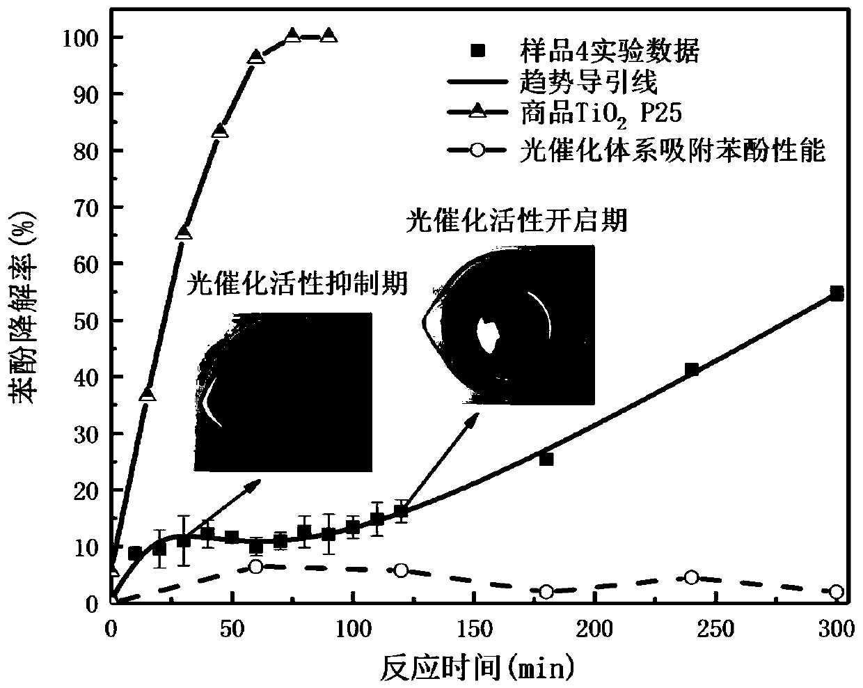
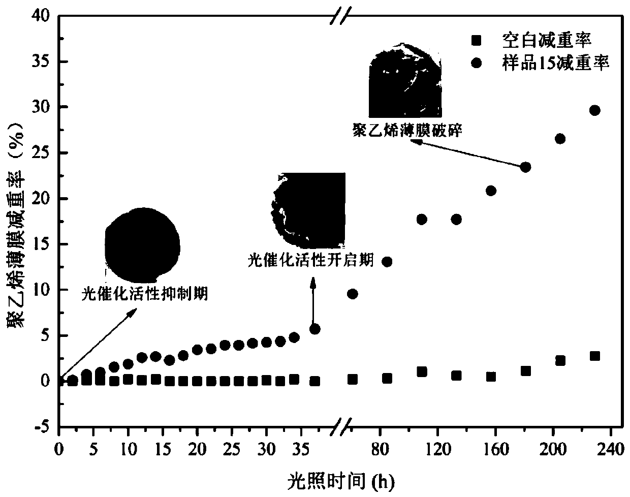
The invention discloses a photocatalytic system with a photoresponse switch and self-indication property as well as a preparation method and application, particularly discloses to the application of the universality of the photocatalytic system to the field of plastic controllable self-indication degradation. The invention relates to a combined photocatalytic system utilizing a photocatalyst, a photo-induced electron-hole consumption agent and a photo-induced electron-hole consumption agent complex, and utilizes color change before and after reaction of the photo-induced electron-hole consumption agent and the photo-induced electron-hole consumption agent complex to construct the photocatalytic system with the photoresponse switch and the self-indication property. In the initial period, the photocatalytic system is in a certain color, does not have photocatalytic activity, is changed in color after being illuminated a certain time, and has efficient photocatalytic activity. The photocatalytic system can serve as a filler to be added into plastic, provides controllable self-indication degradation for the plastic, ensures that the plastic has high stability during a usage period andhas efficient degradation efficiency during an abandoning period, and reminds a consumer of the beginning of the abandoning period of the plastic through the color change.

Description

technical field [0001] The invention belongs to the technical field of photocatalysis, and relates to a photocatalytic system with photoresponsive switch and self-indicating property, its preparation method and its application in the field of plastic degradation, and in particular to the control of the stability period, degradation period and degradation efficiency of plastics by the photocatalysis system. As well as applications in displaying the onset of the degradation phase of plastics through color changes. Background technique [0002] Our country produces 50 million tons of non-decomposable plastic waste every year, which brings a great burden to the environment. Biodegradable plastics can reduce plastic pollution, but biodegradable plastics have not been widely used due to their fragility, low mechanical properties, low heat resistance, and low gas barrier properties. Traditional plastics occupy a huge market share due to their good mechanical properties, thermal st...

Claims


Application Information

Patent Timeline
IPC IPC(8): B01J31/38B01J31/26C08L23/06C08L25/06C08L77/02C08L23/12C08L29/04C08L71/02C08L3/02C08L1/28C08K9/02C08K3/22C08K3/02C08K3/16C08K3/24C08K3/26C08K3/34C08K3/30C08K3/28C08J5/18
CPCB01J31/26B01J31/38B01J35/004C08J5/18C08J2323/06C08J2323/12C08J2325/06C08J2329/04C08J2371/02C08J2377/02C08J2401/28C08J2403/02C08K3/02C08K3/16C08K3/24C08K3/26C08K3/28C08K3/30C08K3/34C08K9/02C08K2003/2241C08K2003/2248C08K2003/2258C08K2003/2293C08K2003/2296C08K2201/014Y02P20/52
Inventor 陈超赵玉婷
Owner EAST CHINA NORMAL UNIV
Why Eureka
Try Eureka