Machining method of durable welding current contact nozzle easy to machine

A manufacturing method and technology of contact tip, which are applied to electrode accessories, characteristics of welding rods, etc., can solve the problems of complex conductive inner core structure, single manufacturing method, low production efficiency, etc., and achieve shortened production time, low production cost and high production efficiency. Effect

Pending Publication Date: 2019-08-02
何强
View PDF3 Cites 3 Cited by
  • Summary
  • Abstract
  • Description
  • Claims
  • Application Information

AI Technical Summary

Problems solved by technology

[0015] In order to overcome the shortcomings of the conductive inner core in the above invention, such as complex structure, single manufacturing method, low production efficiency, and high cost, the present

Method used


Image

  • Machining method of durable welding current contact nozzle easy to machine
  • Machining method of durable welding current contact nozzle easy to machine
  • Machining method of durable welding current contact nozzle easy to machine

Examples


Embodiment 1

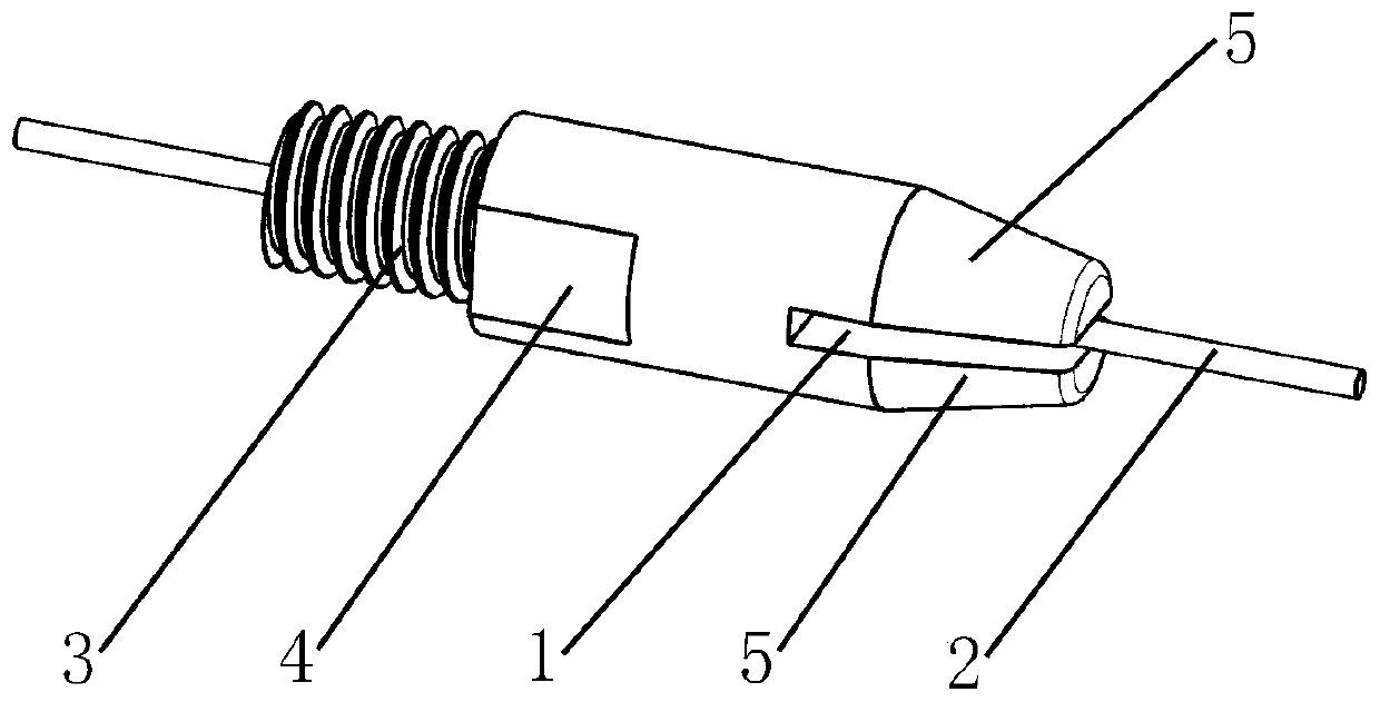
[0054] Embodiment 1: as figure 1 Shown, open a long about 2-30 millimeters long, wide about 0.01-6 millimeter straight shape gap 1 at the front end of common conductive tip. The gap 1 needs to pass through the center of the inner hole of the contact tip, and divide the front end of the contact tip into two upper and lower conductive blocks 5 . In order to avoid the misalignment of gap 1 and the inner hole of the contact tip caused by machining errors and reduce the difficulty of processing, a cutting piece with a thickness slightly larger than the diameter of the inner hole of the contact tip is selected. In this way, the width of the gap 1 cut out is larger than that of the inner hole. Even if there is a deviation during processing, the inner hole of the contact tip and the gap 1 will not be misaligned. Finally, the upper and lower conductive blocks 5 are properly pressed inward, so that the heads of the two conductive blocks 5 are closed, and the easy-to-process and durable...

Embodiment 2

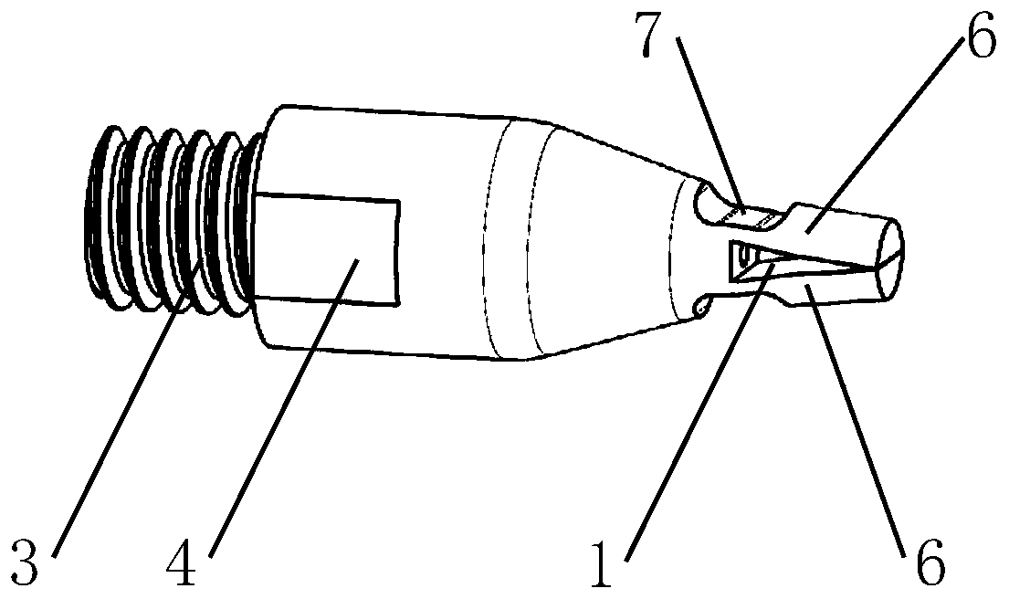
[0055] Embodiment 2: as figure 2 As shown, in this embodiment, high-strength, high-conductivity copper alloy materials such as chrome-zirconium copper, phosphor bronze, tin bronze, etc. should be selected to make easy-to-process and durable contact tips. In order to facilitate processing, the front end of the contact tip is first processed into a cylinder, the cylinder is about 2-30 mm long, and the diameter of the cylinder is 2.5-5 times that of the welding wire 2. Two mutually symmetrical gaps 7 are opened at the rear end of the cylinder, so that the material thickness of the remaining part between the two gaps 7 is 2-4 times of the diameter of the welding wire 2 . Process the notch 1 with a cutting sheet, the notch 1 passes through the center of the inner hole of the conductive tip, and is parallel to the notch 7, the heel of the notch 1 is in the middle or the middle rear of the notch 7, the purpose is to press the elastic conductive block 6 When closed, the heel of the ...

Embodiment 3

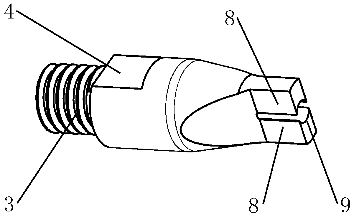
[0057] Embodiment 3: as image 3As shown, in order to further increase the service life of the contact tip, more material must be provided for the wear of the contact tip. The diameter of the cylinder at the front end of the contact tip is increased to 3.2-5 times the diameter of the welding wire 2, and the length of the cylinder is about 4-15 mm. Cut off the material on both sides of the cylinder, first cut 2-10 mm straight from the front to the back, and then cut obliquely toward the outer edge of the contact tip. The parts cut off on both sides have a symmetrical structure. The remaining part of the material in the middle forms a thickened conductive block 8, and the width of the thick conductive block 8 is slightly smaller than the diameter of the welding wire 2. There is a positioning arc surface 9 inside the thickened conductive block 8, and the positioning arc surface 9 constrains the welding wire 2 to ensure the accuracy of the wire output. The heads of the upper and...


PUM


Abstract

The invention discloses a machining method of durable welding current contact nozzle easy to machine. Conductive blocks are obtained through a mode of machining a seam in the front end of the currentcontact nozzle, or is obtained through a mode of machining the thick seam and obtaining a gap, or is obtained through a mode of carrying out interference connection on two conductive block combinationblocks; according to the durable welding current contact nozzle easy to machine, the gap is formed in the front end of the current contact nozzle, so that the current contact nozzle forms the upper conductive block and the lower conductive block; according to the durable welding current contact nozzle easy to machine, materials on the two sides of the front end of the current contact nozzle are removed, a machining line passes through an edge of a welding stick passing hole to form a thickened conductive block, and the width of the thickened conductive block is narrower than that of the welding stick; and according to the durable welding current contact nozzle easy to machine, an elongated cylinder is arranged at the front end of the current contact nozzle, a large via hole is formed in the center of the current contact nozzle, a head part of the cylinder is a conductive head, a conductive hole is formed in the center of the conductive head, and the conductive hole and the large via hole are positioned on the same axis.

Description

[0001] Technical field [0002] The invention relates to various manufacturing methods of durable welding contact tips, and durable welding contact tips manufactured according to these several manufacturing methods. Its characteristic is that the front end of the contact tip has a straight gap, which divides the tip into upper and lower conductive blocks, and the conductive block constrains the welding wire, conducts electricity for the welding wire, and wears the welding wire. The gap of the contact tip is obtained by cutting, interfering with the conductive combination block, and first forging the thick gap, and then rolling it into a thin and long gap. The contact tip not only has a long service life, but also has excellent electrical conductivity, which not only saves the use cost, but also improves the welding quality. The biggest feature of the contact tip is its extremely simple structure, and it is easier to process and manufacture in technology. Compared with the prior...

Claims


Application Information

Patent Timeline
IPC IPC(8): B23K9/26B23P15/00
CPCB23K9/26B23P15/00
Inventor 何强汪年成何珍
Owner 何强
Why Eureka
Try Eureka