Smoke waste heat exchanger

A flue gas waste heat and exchanger technology, applied in the field of exchangers, can solve the problems of low exchange efficiency of boiler waste heat exchangers, and achieve the effects of increasing heat exchange efficiency and increasing heat exchange time

Pending Publication Date: 2019-08-02
四川陆亨能源科技有限公司
View PDF0 Cites 0 Cited by
  • Summary
  • Abstract
  • Description
  • Claims
  • Application Information

AI Technical Summary

Problems solved by technology

[0006] The purpose of the present invention is to provide a flue gas waste heat exchanger to solve the problem of low exchange efficiency of the existing boiler waste heat exchanger

Method used


Image

  • Smoke waste heat exchanger
  • Smoke waste heat exchanger
  • Smoke waste heat exchanger

Examples


Embodiment Construction

[0027] The specific embodiments of the present invention are described below so that those skilled in the art can understand the present invention, but it should be clear that the present invention is not limited to the scope of the specific embodiments. For those of ordinary skill in the art, as long as various changes Within the spirit and scope of the present invention defined and determined by the appended claims, these changes are obvious, and all inventions and creations using the concept of the present invention are included in the protection list.

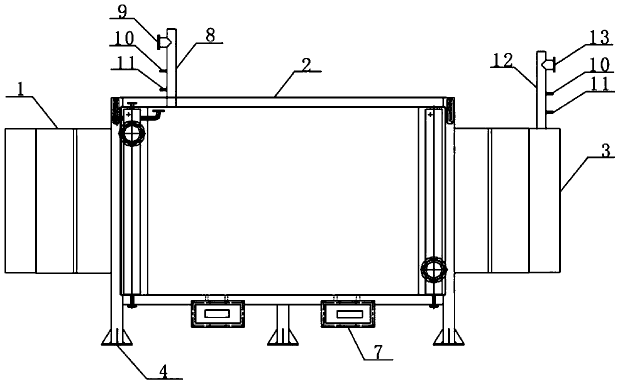
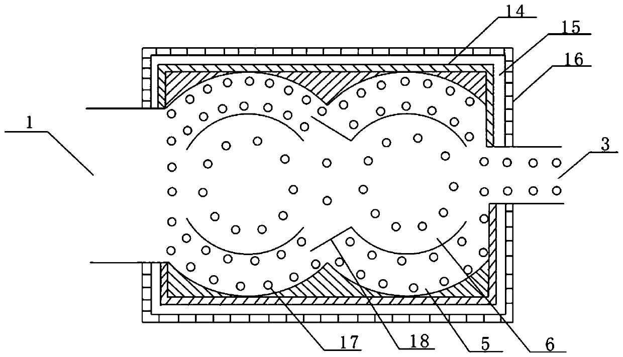
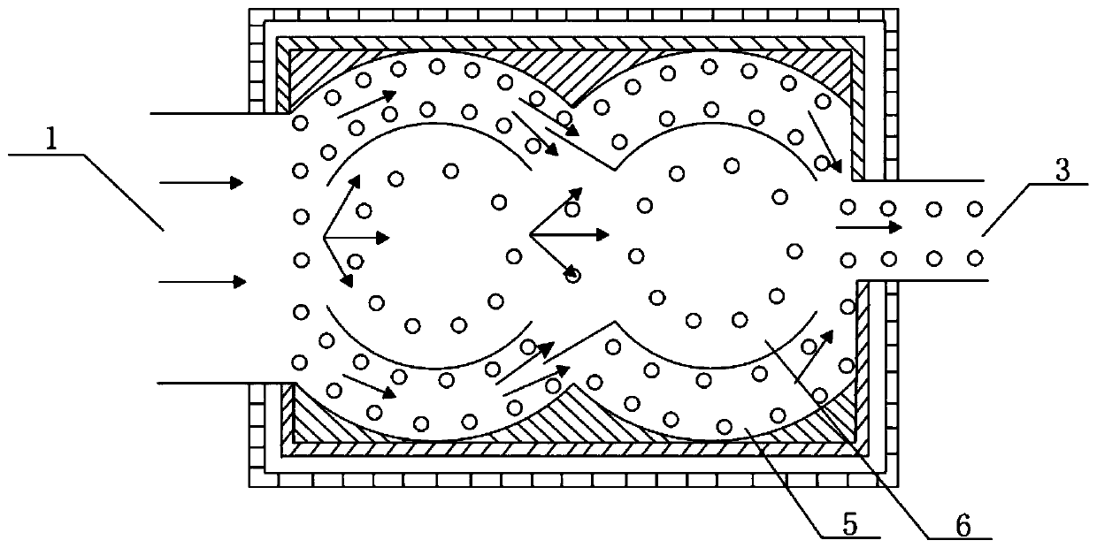
[0028] According to an embodiment of the present application, refer to figure 1 , the flue gas waste heat exchanger of this program includes a flue gas inlet 1 arranged at one end of the casing 2, and a flue gas outlet 3 opposite to the flue gas inlet 1; The heat exchange smoke cavity is connected.

[0029] Four support columns 4 are arranged around the casing 2 to support the casing 2; two ash outlets are provided at the ...


PUM


Abstract

The invention discloses a smoke waste heat exchanger. The smoke waste heat exchanger comprises a smoke inlet formed in one end of a shell and a smoke outlet opposite to the smoke inlet. The smoke inlet and the smoke outlet communicate with a heat-exchange smoke cavity in the shell. The heat-exchange smoke cavity comprises inner circular smoke cavities and outer circular smoke cavities arranged around the inner circular smoke cavities. A plurality of heat-exchange water pipes are evenly distributed in the inner circular smoke cavities and the outer circular smoke cavities. The inner circular smoke cavities include the first inner circular smoke cavity and the second inner circular smoke cavity. The first inner circular smoke cavity comprises two first inner circular arc plates. A connectingline of upper endpoints A3 and A4 of the inner circular arc plate is parallel to a connecting line of B3 and B4, and a connecting line of upper endpoints A1 and A2 of the second inner circular arc plate is parallel to a connecting line of B1 and B2. The outer circular smoke cavities include the first outer circular smoke cavity and the second outer circular smoke cavity.

Description

technical field [0001] The invention belongs to the technical field of exchangers, and in particular relates to a flue gas waste heat exchanger. Background technique [0002] During the smelting and production process of ferrosilicon furnace, a large amount of high-temperature flue gas entrained with fine dust particles is produced. To produce 1 ton of 75% ferrosilicon, theoretically about 1500-2000Nm 3 Furnace gas, the main component of flue gas is N 2 , O 2 , CO 2 、H 2 O, due to the large air excess coefficient, it is basically close to the air composition. [0003] SO in flue gas 2 The content depends on the amount of sulfur brought into the raw material, mainly determined by the sulfur content of the reducing agent. The amount of sulfur brought in by 1 ton of 75% ferrosilicon raw material is generally about 5-10kg, of which 90% is burned into SO 2 After entering the flue gas, the sulfur content of the flue gas in the semi-closed electric furnace is generally 0.1 ...

Claims


Application Information

Patent Timeline
Patent Type & Authority Applications(China)
IPC IPC(8): F28D21/00F28F9/00F28F9/24F28F27/00F27D17/00
CPCF27D17/004F28D21/00F28F9/00F28F9/24F28F27/00Y02P10/25
Inventor 陈晨孙积文彭加华陈祥顺胡宝义陈文政
Owner 四川陆亨能源科技有限公司
Why Eureka
Try Eureka