

Compressor characteristic prediction method based on modified gas seal leakage amount influence numerical model
A numerical model and characteristic prediction technology, applied in jet engine testing, gas turbine engine testing, prediction, etc., can solve problems such as gas leakage, compressor performance prediction result deviation, etc., to achieve reduced deviation, good numerical calculation convergence, and reduced Computational resource and time consumption effects
- Summary
- Abstract
- Description
- Claims
- Application Information
AI Technical Summary
Problems solved by technology
Method used
Image

Examples
specific Embodiment approach 1
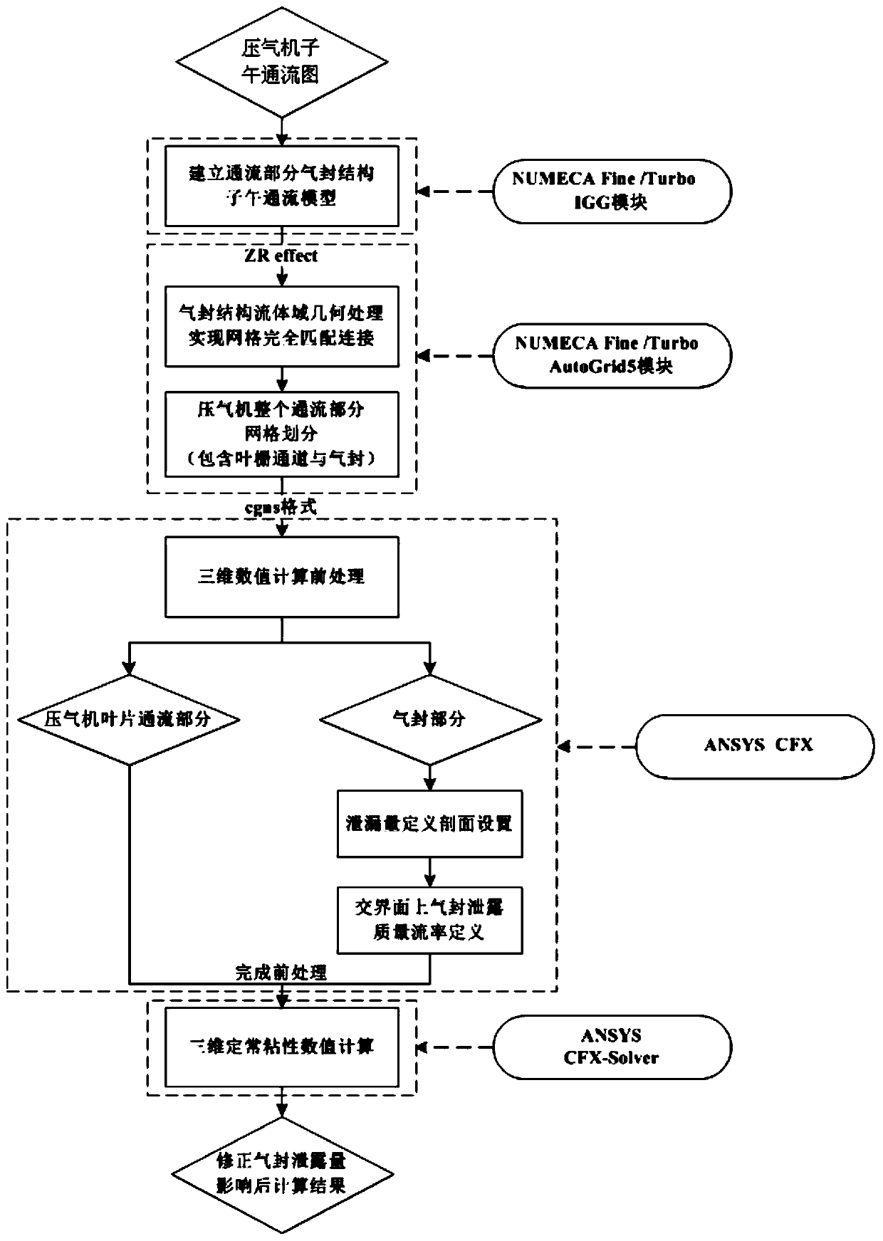
[0028] Specific implementation mode one: combine figure 1 , figure 2 To describe this embodiment, the method for predicting the characteristics of a compressor based on the numerical model of the influence of the corrected gas seal leakage amount given in this embodiment specifically includes the following steps:
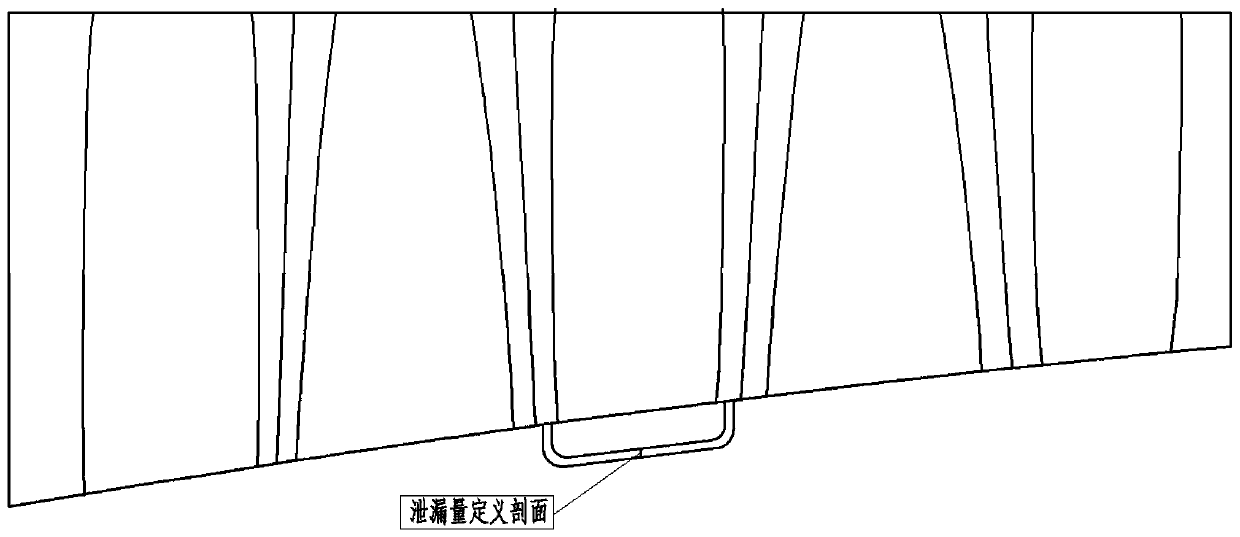
[0029] Step 1: Carry out air seal structure processing according to the meridian flow diagram of the compressor, and establish a meridian flow model of the air seal structure of the flow part located at the root of the stator blade (such as figure 2 As shown), the meridional flow model of the gas seal structure of the flow part has the required section for the definition of leakage;
[0030] Step 2. Import the established meridional flow model of the gas seal structure of the flow part into the grid division tool, and create radial lines of the meridian flow of the compressor at each inlet and outlet positions of the gas seal structure to realize the air seal str...
specific Embodiment approach 2
[0048] Embodiment 2: The difference between this embodiment and Embodiment 1 is that the step 1 is performed in the IGG module of NUMECAFine / Turbo (a high-performance kinetic analysis software launched by NUMECA Company) software.
[0049] Other steps and parameters are the same as those in the first embodiment.
specific Embodiment approach 3
[0050] Embodiment 3: The difference between this embodiment and Embodiment 2 is that the AutoGrid5 module in the NUMECA Fine / Turbo software is used as the grid division tool in Step 2 and Step 3.
[0051] Other steps and parameters are the same as in the second embodiment.
PUM
 Abstract
Description
Claims
Application Information