
Input voltage divider circuit and overvoltage protection switch

A technology of input voltage and voltage dividing circuit, which is applied in the direction of overvoltage-responsive protection, circuit devices, emergency protection circuit devices, etc., and can solve problems that affect user experience and are prone to false shutdowns

Active Publication Date: 2021-02-19
SHANGHAI AWINIC TECH CO LTD
View PDF2 Cites 0 Cited by
  • Summary
  • Abstract
  • Description
  • Claims
  • Application Information

AI Technical Summary

Problems solved by technology

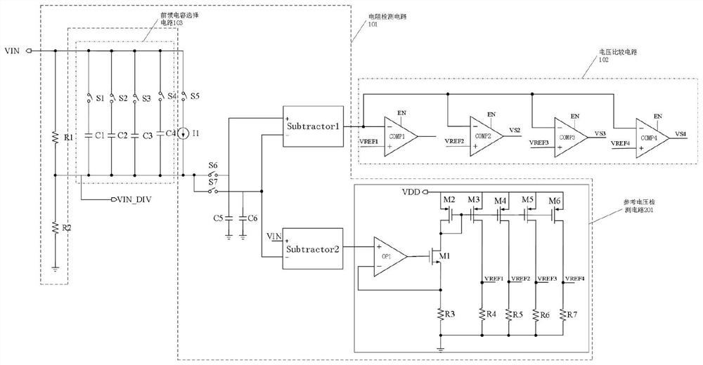
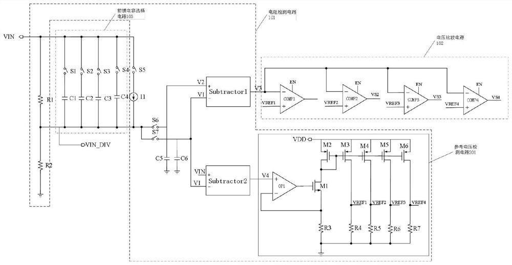
[0003] The overvoltage protection switch is a device that reduces the voltage of the controlled device or disconnects the power supply when the external input voltage exceeds the preset voltage threshold. To protect the stress of the post-stage chip of the switch, but during the use of the existing overvoltage protection switch, due to the mismatch between the feedforward capacitor and the voltage dividing resistor, it is very easy to turn off by mistake, that is, the input voltage value is lower than the preset voltage In the protection range, the overvoltage protection switch will also be turned off, and the turn-off accuracy of the overvoltage protection switch directly affects the user's experience with the device

Method used


Image

  • Input voltage divider circuit and overvoltage protection switch
  • Input voltage divider circuit and overvoltage protection switch
  • Input voltage divider circuit and overvoltage protection switch

Examples


Embodiment Construction

[0076] The following will clearly and completely describe the technical solutions in the embodiments of the present invention with reference to the accompanying drawings in the embodiments of the present invention. Obviously, the described embodiments are only some, not all, embodiments of the present invention. Based on the embodiments of the present invention, all other embodiments obtained by persons of ordinary skill in the art without making creative efforts belong to the protection scope of the present invention.

[0077] In this application, the term "comprises", "comprises" or any other variation thereof is intended to cover a non-exclusive inclusion such that a process, method, article, or apparatus comprising a set of elements includes not only those elements, but also includes none. other elements specifically listed, or also include elements inherent in such a process, method, article, or apparatus. Without further limitations, an element defined by the phrase "com...


PUM


Abstract

The invention provides an input voltage divider circuit, comprising: a resistance detection circuit, a voltage comparison circuit and a feedforward capacitor selection circuit, through which the resistance detection circuit detects the resistance value of the lower divider resistor in the input voltage divider module, and obtains the lower divider resistance through conversion. The voltage value of the voltage divider resistor; the voltage comparison circuit compares the received voltage value corresponding to the lower voltage divider resistor with each reference voltage, and outputs a corresponding electrical signal, which is used to control the corresponding switch in the feedforward capacitor selection circuit to select the corresponding feedforward capacitor. By applying the input voltage divider circuit provided by the present invention, when a surge voltage occurs, the corresponding feedforward capacitor is selected according to the resistance value of the lower divider resistor, which effectively reduces the response time of the input voltage divider circuit and greatly reduces the The turn-off time of the overvoltage protection switch makes the turn-off time of the overvoltage protection switch more reasonable, and reduces the probability of the overvoltage protection switch being turned off by mistake.

Description

technical field [0001] The invention relates to the technical field of semiconductor integrated circuits, in particular to an input voltage divider circuit and an overvoltage protection switch. Background technique [0002] When a surge voltage is generated in various integrated circuit boards, the surge voltage will damage the performance of the semiconductor device in the electronic equipment and reduce the life of the semiconductor device. There are many factors, such as lightning strikes, electrostatic discharges and industrial events, etc.; the surge voltage is characterized by a very short generation time, usually at the microsecond level, and its voltage and current are many times the normal value. In order to reduce the impact of the surge voltage on To prevent damage to electronic equipment, overvoltage protection switches (Over Voltage Protection, OVP) are widely used in various electronic equipment. [0003] The overvoltage protection switch is a device that redu...

Claims


Application Information

Patent Timeline
Patent Type & Authority Patents(China)
IPC IPC(8): H02H3/05H02H3/20
CPCH02H3/05H02H3/20
Inventor 胡建伟罗旭程程剑涛杜黎明孙洪军乔永庆
Owner SHANGHAI AWINIC TECH CO LTD
Learn More