Method for correcting vortex light wave front distortion based on phase difference algorithm

A technology of wavefront distortion and vortex light, which is applied in electromagnetic receivers, free space transmission, etc., can solve the problems that vortex beams cannot be fully and effectively corrected, and the difficulty of experiments increases, so as to achieve comprehensive and effective corrections and reduce the difficulty of experiments Effect

Active Publication Date: 2019-08-02
XIAN UNIV OF TECH
View PDF4 Cites 15 Cited by
  • Summary
  • Abstract
  • Description
  • Claims
  • Application Information

AI Technical Summary

Problems solved by technology

[0004] The purpose of the present invention is to provide a method for correcting the wavefront distortion of vortex light based on phase difference algorithm, which solves the problem that the current wavefront correction technology will make the experiment more difficult, and the vortex beam cannot be fully and effectively corrected

Method used


Image

  • Method for correcting vortex light wave front distortion based on phase difference algorithm
  • Method for correcting vortex light wave front distortion based on phase difference algorithm
  • Method for correcting vortex light wave front distortion based on phase difference algorithm

Examples


Embodiment 1

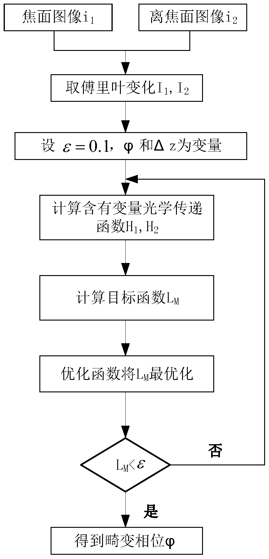
[0093] This embodiment discloses a method for correcting wavefront distortion of vortex light based on a phase difference algorithm, which is specifically implemented according to the following steps:

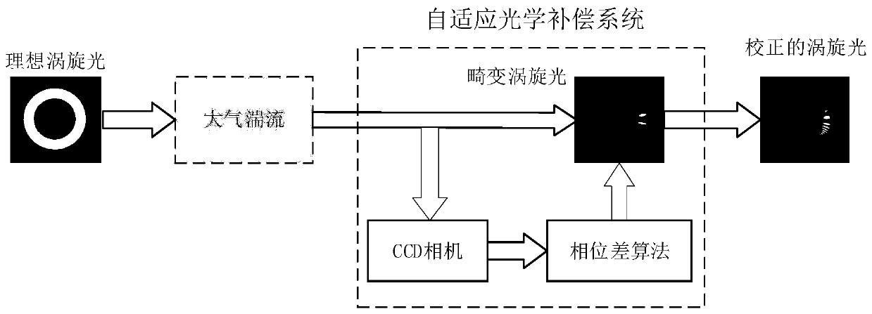
[0094] Taking the adaptive correction of a single-mode vortex beam as an example, the fractal method is used to simulate the phase screen of atmospheric turbulence, and the atmospheric structure constant is In order to introduce phase distortion;

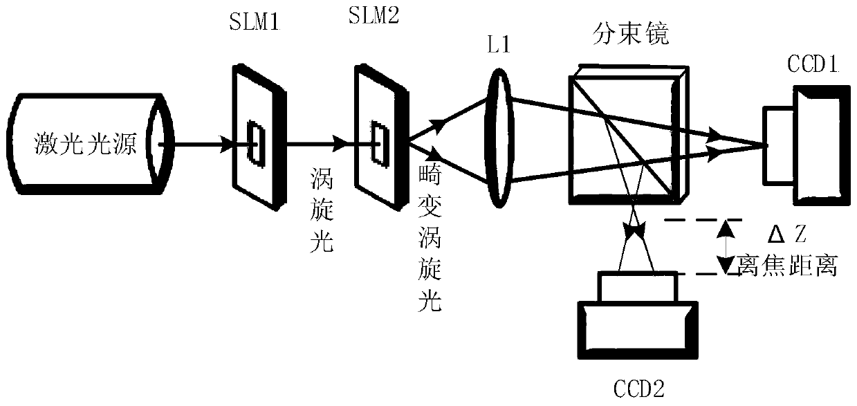
[0095] Step 1: collect the light intensity information of the initial light field and the distorted light field;

[0096] Step 1.1: initial light field,

[0097] Collect an ideal Laguerre-Gaussian beam u without distortion i (x,y):

[0098] The Laguerre-Gaussian beam in the input light field transmitted by the vortex optical communication system is at the emission point z=0, and the expression of the radial index p=0 is:

[0099]

[0100] Among them, p represents the radial index, l represents the topological charge, ω 0 Ind...

Embodiment 2

[0131] A method for correcting wavefront distortion of vortex light based on a phase difference algorithm, specifically implemented according to the following steps:

[0132] Taking the adaptive correction of multi-mode multiplexing vortex beams as an example, the fractal method is used to simulate the phase screen of atmospheric turbulence, and the atmospheric structure constant is In order to introduce phase distortion;

[0133] Step 1: collect the light intensity information of the initial light field and the distorted light field;

[0134] Step 1.1: initial light field,

[0135] Collect an ideal Laguerre-Gaussian beam u without distortion i (x,y):

[0136] The Laguerre-Gaussian beam in the input light field transmitted by the vortex optical communication system is at the emission point z=0, and the expression of the radial index p=0 is:

[0137]

[0138] Among them, p represents the radial index, l represents the topological charge, ω 0 Indicates the beam waist ra...


PUM


Abstract

The invention discloses a method for correcting the vortex light wave front distortion based on a phase difference algorithm. The method is specifically implemented according to the following steps of1, collecting the light intensity information of an initial light field and a distorted light field; 2, performing the adaptive phase correction on a distorted vortex light beam, solving the phase ofthe distorted vortex light beam, and 2.3, correcting the distorted vortex light beam; and step 3, evaluating the correction effect of the vortex light, thereby comparing the spiral spectrograms of the vortex light beams with different topological charges 1 before and after correction, and analyzing the mode crosstalk of the vortex light before and after correction. According to the method for correcting the vortex light wave front distortion based on the phase difference algorithm, the experiment difficulty of the wave front correction technology is reduced, and the vortex light beam can be comprehensively and effectively corrected.

Description

technical field [0001] The invention belongs to the technical field of free space optical communication, and in particular relates to a method for correcting vortex optical wavefront distortion based on a phase difference algorithm. Background technique [0002] The vortex beam is a new type of beam with a unique helical wavefront phase distribution and a new degree of freedom, namely orbital angular momentum. Compared with plane waves and spherical waves, due to the phase singularity in the center of the vortex beam, its light intensity cross-section will present a ring with a dark spot in the center. The expression of the vortex beam has a phase factor exp(ilθ), each photon in the beam carries the orbital angular momentum lh, where l is called the topological charge, θ is the azimuth angle, theoretically the orbital angular momentum of the vortex beam It can take any non-zero integer, that is, infinitely multi-dimensional, and the vortex beams of different orders are orth...

Claims


Application Information

Patent Timeline
Patent Type & Authority Applications(China)
IPC IPC(8): H04B10/11H04B10/60
CPCH04B10/11H04B10/60
Inventor 柯熙政崔娜梅
Owner XIAN UNIV OF TECH
Why Eureka
Try Eureka