Shredding machine blade and machining process thereof

A shredder and blade technology, which is applied in the direction of mechanical material recovery, recycling technology, grain processing, etc., can solve the problems that the shredder blade is prone to cracks, the particle size does not meet the requirements, and the service life of the blade is increased. Easy to install up and down, small slip coefficient, and increased service life

Pending Publication Date: 2019-08-06
安徽华天机械股份有限公司
View PDF2 Cites 1 Cited by
  • Summary
  • Abstract
  • Description
  • Claims
  • Application Information

AI Technical Summary

Problems solved by technology

[0009] The invention provides a shredder blade. By arranging a plurality of cutter heads and designing grooves at the joints of each cutter head, the purpose is to solve the problem that cracks are easily generated in the process of using the shredder blade and the material is shredded. Particle size does not meet the requirements, while increasing the service life of the blade, it also ensures that the crushed material particles are finer
[0010] The invention provides a shredder blade. By optimizing the design of the installation hole of the blade, the problem that the installation hole of the shredder blade is not firmly installed and easy to wear is solved, and the wear at the edges and corners of the blade connection hole is reduced. Ensure blades are evenly stressed

Method used


Image

  • Shredding machine blade and machining process thereof
  • Shredding machine blade and machining process thereof
  • Shredding machine blade and machining process thereof

Examples


Embodiment 1

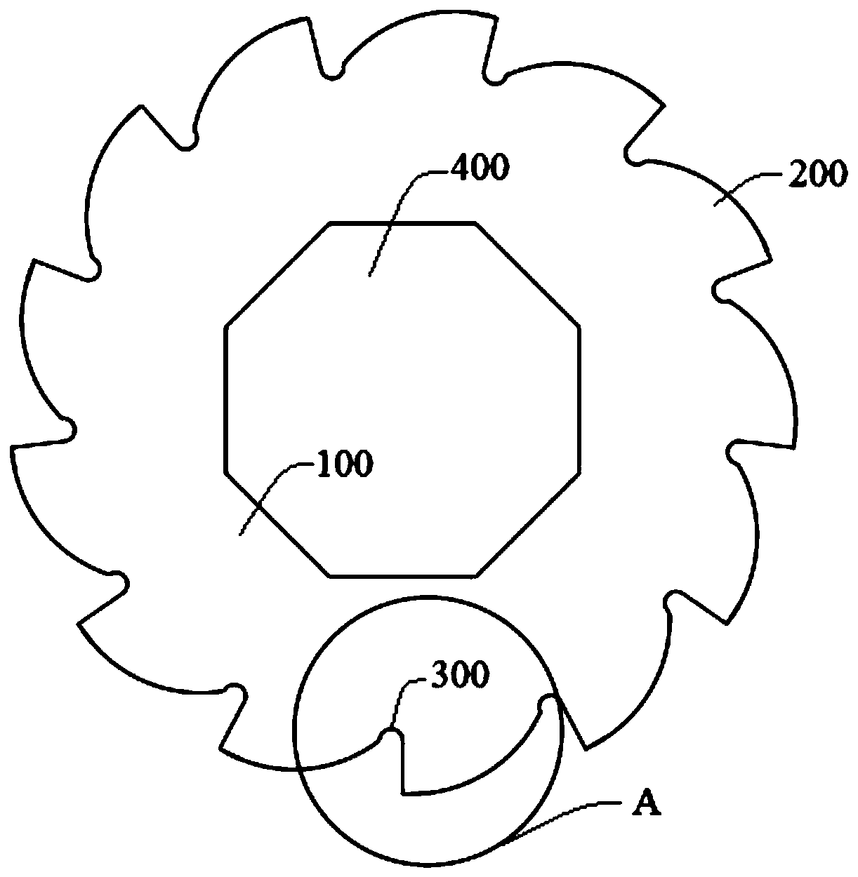
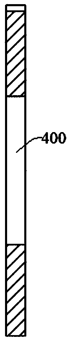
[0053] Please refer to figure 1 and figure 2 , the shredder blade of this embodiment includes a blade body 100, and the blade body 100 is provided with a cutter head 200, a groove 300 and a mounting hole 400, wherein n cutter heads are provided, n=13, and the groove 300 is located in At the joint between adjacent cutter heads 200, the mounting hole is a regular octagon, and the radius of the regular octagon is r 0 = 50mm.

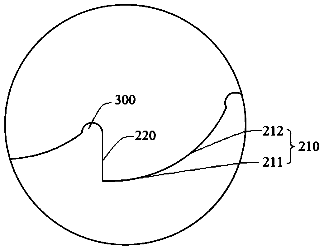
[0054] Specifically, combining image 3 As shown, the cutter head 200 includes a blade 210 and a blade back 220. The cutting angle of the blade 210 is 25° to 35°, and the blade 210 is formed by connecting multiple small arc-shaped blades, so that the materials are subjected to different pressures during the shearing process. The shear force in the direction, and then the size of the crushed material is smaller; the radius of the circle where the arc-shaped blade is located is different, and in the processing direction of the blade to shred the material,...

Embodiment 2

[0066] This embodiment is basically the same as Embodiment 1, except that the groove surface of the groove 300 is a spherical crown surface.

[0067] The groove surface of the groove 300 in this embodiment is a spherical crown surface. While the spherical crown surface has the advantages of a circular arc surface, the spherical crown surface can also disperse the received impact force to the surroundings evenly, and the force direction of each point can extend to the spherical surface. The spherical center of the crown ensures uniform stress at each point, reduces impact cracks, and further enhances the impact resistance of the blade. to combine Figure 5 As shown, the groove surface is a groove 300 of a spherical crown surface, the notch of the groove 300 is arc-shaped, and the section of the notch is a radius r 1 = r 0 / n semicircle, about r 1 =3.85mm, the distance from the bottom of the spherical crown groove to the highest point of the groove h=r 0 / n+0.3, ie h=4.15mm....

Embodiment 3

[0078] This embodiment is basically the same as Embodiment 1, except that this embodiment is a shredder blade in which the length and dimension of the blade 210 in Embodiment 1 are doubled, the angle dimension remains unchanged, and the components of the forged blank And the mass percentage is different.

[0079] Specifically, the radius of the regular octagonal mounting hole in this embodiment is r 0 =100mm; the cutting angle of the cutting edge 210 is 25°~35°, and the radius of the circle where the first cutting edge 211 is located is R 1 =222mm, the arc length is 11.52±0.3mm, the radius of the circle where the second cutting edge 212 is located is R 2 =74mm, the arc length is 77.5±0.3mm, where R 1 = 3R 2 The connection between the first cutting edge 211 and the second cutting edge 212 of the present embodiment is smooth, and the radius ratio of the circle where each small arc-shaped blade of the tool of the present invention is on the surface is reasonable, and after bei...


PUM

PropertyMeasurementUnit
radiusaaaaaaaaaa

Abstract

The invention discloses a shredding machine blade and a machining process thereof, and belongs to the technical field of tools. The shredding machine blade comprises a blade body, wherein the blade body is provided with blade heads, grooves and a mounting hole, the n blade heads are uniformly arranged at the edge of the blade body, 8<=n<=15, and preferably, n=13; the grooves are arranged at the joints between the adjacent blade heads, the groove surface of each groove is set as an arc surface or a spherical crown surface, the grooves are used for dispersing the impact force of materials on thejoints of the adjacent blade heads, it is guaranteed that the the impact force at all points on the groove surfaces is uniform, and the blade does not crack easily; cutting edges of the blade heads are composed of multiple arc cutting edge bodies with different radians so that it can be guaranteed that the sizes of shredded materials are smaller; the mounting hole is set as a regular octagon; andlinear cutting is used for moulding and forming the blade, and meanwhile the machining process of the blade is optimized. According to the shredding machine blade, in the blade shape optimization design, it is ensured that the sizes of the shredded materials are smaller, the service life of the blade is prolonged, and mass production and machining of enterprises are facilitated.

Description

technical field [0001] The invention belongs to the technical field of knives, and more specifically relates to a shredder blade and its processing technology, which are used for crushing, tearing and extruding to reduce the size of materials. This shredder blade is widely used in waste plastics , Waste rubber, wood and other bulky waste shredding. Background technique [0002] The shredder blade is one of the most important accessories on the shredder. Its quality directly affects the processing cycle of the machine to waste. Small material size, widely used in crushing waste plastics, waste rubber, wood and other bulky wastes. The part used to cut the material on the shredder blade can be called the cutter head. Generally, there are multiple cutter heads for cutting materials on the blade, but there are mostly sharp transitions between the cutter heads. During use, it is prone to cracks caused by collisions, which reduces the service life of the blade. At the same time,...

Claims


Application Information

Patent Timeline
Patent Type & Authority Applications(China)
IPC IPC(8): B02C18/18B29B17/04B23P15/28
CPCB02C18/18B23P15/28B29B17/04Y02W30/52Y02W30/62
Inventor 陶鹏陶民陶贵勇
Owner 安徽华天机械股份有限公司
Why Eureka
Try Eureka