Device for detecting optical crosstalk transmittance between optical fibers in optical fiber image transmission component

A technology of optical fiber image transmission and transmittance, which is applied in the direction of testing optical fiber/optical waveguide equipment, measuring devices, and testing optical performance. Results and other issues, to achieve the effect of intuitive detection results, high test efficiency, and improved detection efficiency

Active Publication Date: 2019-08-06
CHINA BUILDING MATERIALS ACAD
View PDF7 Cites 5 Cited by
  • Summary
  • Abstract
  • Description
  • Claims
  • Application Information

AI Technical Summary

Problems solved by technology

From the detection point of view, there are three obvious deficiencies in using the knife-edge response value to characterize the optical crosstalk performance: first, the measurement value is inaccurate, the test conditions are inconsistent with the actual use environment, and the sample preparation is complicated and has a great influence on the measurement results. This leads to problems with the stability or reliability of the test results. There are often large differences in the results of multiple detections of the knife-edge response value of a sample, and the maximum deviation can exceed 50%.
For optical fiber image transmission components, there is a range of testing thickness requirements, and products with a thickness higher than a certain thickness cannot be directly detected.
In this way, whether it is an optical fiber straight plate, an optical fiber inverter or a fiber optic cone product, it is an indirect test characterization, and only a part of the tested product can be tested, and the section position often cannot represent the entire tested product. Optical Crosstalk Performance
The third is that there is only one such knife-edge response measuring equipment in China at present, and the test accuracy will seriously decrease with the aging of the equipment, and it will gradually be eliminated.

Method used


Image

  • Device for detecting optical crosstalk transmittance between optical fibers in optical fiber image transmission component
  • Device for detecting optical crosstalk transmittance between optical fibers in optical fiber image transmission component
  • Device for detecting optical crosstalk transmittance between optical fibers in optical fiber image transmission component

Examples


Embodiment 1

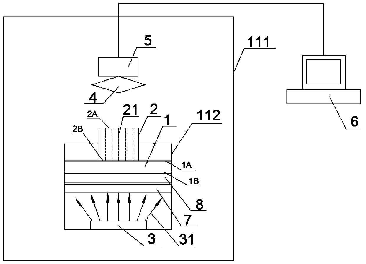
[0118] A method for detecting optical crosstalk transmittance between optical fibers in an optical fiber image transmission element by using the aforementioned device, specifically comprising the following steps: 1) starting the control software of the contrast test system of the optical fiber image transmission element;

[0119] 2) Inject an appropriate amount of coupling oil on the USAF test target, and put it into the optical fiber image transmission element, so that the optical fiber and the test target are closely bonded;

[0120] 3) Open the operation door of the dark box, and place the fitted test target and optical fiber image transmission components on the optical work platform; the test target and optical fiber image transmission components have been relatively positioned by the fixture, and only need to place the fixture on the workbench on the positioning pin;

[0121] 4) Close the operation door of the dark box, so that the optical workbench and the entire test sy...

Embodiment 2

[0128] A method for detecting the transmittance of optical crosstalk between optical fibers in an optical fiber image transmission component is verified for the accuracy of the detection results, which specifically includes the following steps:

[0129] 1) Start the control software of the optical fiber imaging component contrast test system;

[0130] 2) Inject an appropriate amount of coupling oil on the USAF test target, and put it into the optical fiber image transmission element, so that the optical fiber and the test target are closely bonded;

[0131] 3) Open the operation door of the dark box, and place the fitted test target and optical fiber image transmission components on the optical work platform; the test target and optical fiber image transmission components have been relatively positioned by the fixture, and only need to place the fixture on the workbench on the positioning pin;

[0132] 4) Close the operation door of the dark box, so that the optical workbench...


PUM


Abstract

The invention discloses a device for detecting optical crosstalk transmittance between optical fibers in an optical fiber image transmission component. The device comprises a detection system and a control system. The detection system comprises a cabinet body, a light source, a measuring template and an image acquisition mechanism, wherein the cabinet body can be used to prevent external light from entering into the detection system and provide a light avoiding environment for detection; the light source is used for providing light required during detection; the measuring template provides a standard pattern for detection; and the image acquisition mechanism is used to collect images formed by the standard pattern on the optical fiber image transmission component to be tested. The controlsystem comprises an image data processing unit and a control unit. The device adopts the measuring template with the standard pattern so that the standard pattern is transmitted by the optical fiber image transmission component to be tested and then forms the image, and image data is analyzed to obtain a transmittance value used for representing stray light crosstalk performance between the optical fibers. By using the device, reliability and accuracy of a detection result can be improved, detection cost is reduced and dependence of the detection result on an external condition is decreased.

Description

technical field [0001] The invention relates to an automatic detection device, in particular to a device for detecting the optical crosstalk transmittance between optical fibers in an optical fiber image transmission element. Background technique [0002] At present, the ultra-second-generation and third-generation low-light night vision technology is developing towards 4G technology, which requires the spectral response wavelength to extend to the long-wave and short-wave directions, the imaging quality factor to exceed 1800, the imaging resolution higher than 57lp / mm and higher imaging resolution . The stray light crosstalk between optical fibers is the main factor that deteriorates imaging clarity and reduces contrast. How to characterize the performance of stray light crosstalk in optical fiber imaging components becomes an important issue. [0003] The current characterization method related to the evaluation of optical crosstalk performance is the knife-edge response...

Claims


Application Information

Patent Timeline
Patent Type & Authority Applications(China)
IPC IPC(8): G01M11/02
CPCG01M11/0257G01M11/0285G01M11/33
Inventor 黄永刚周游王久旺付杨贾金升
Owner CHINA BUILDING MATERIALS ACAD
Why Eureka
Try Eureka