
Dynamic road traffic signal control system and method

A technology for traffic signals and control systems, applied in the field of dynamic road traffic signal control systems, can solve problems such as adding ground obstacles, increasing driving risks, and difficult to use roads, and reducing maintenance and repair costs, accuracy and flexibility. Improve and avoid the effect of collision and extrusion

Active Publication Date: 2019-08-09
SOUTHWEST JIAOTONG UNIV
View PDF8 Cites 1 Cited by
  • Summary
  • Abstract
  • Description
  • Claims
  • Application Information

AI Technical Summary

Problems solved by technology

[0003] At present, traffic signal devices using wireless communication technology have appeared, such as the "Wireless Traffic Signal Light Management System" disclosed in Chinese Patent Application No. 201811560050.X. The management system focuses on the operation and management of traffic signal lights set at intersections , only optimized from the perspective of construction and technology, there is no direct solution to the problem of low utilization of road space
[0004] Another example is "a light control device for tidal lanes" disclosed in Chinese patent application No. 201811579784.2. Although the light control system described in this patent is buried, it adopts the way of raising and lowering the warning parts to realize the opening and closing of tidal lanes. Closed, due to changes in the depth of the mechanism and the ground space, there is a high construction cost, and there is a possibility of increasing the risk of driving due to new ground obstacles, and it is difficult to use on the roads that have been built.
[0005] The road signal systems described in the above two patents are either based on the traditional road signal system, improve the control combined with real-time data, or use a device with low flexibility for tidal lane guidance. lacking

Method used


Image

  • Dynamic road traffic signal control system and method
  • Dynamic road traffic signal control system and method
  • Dynamic road traffic signal control system and method

Examples


Embodiment Construction

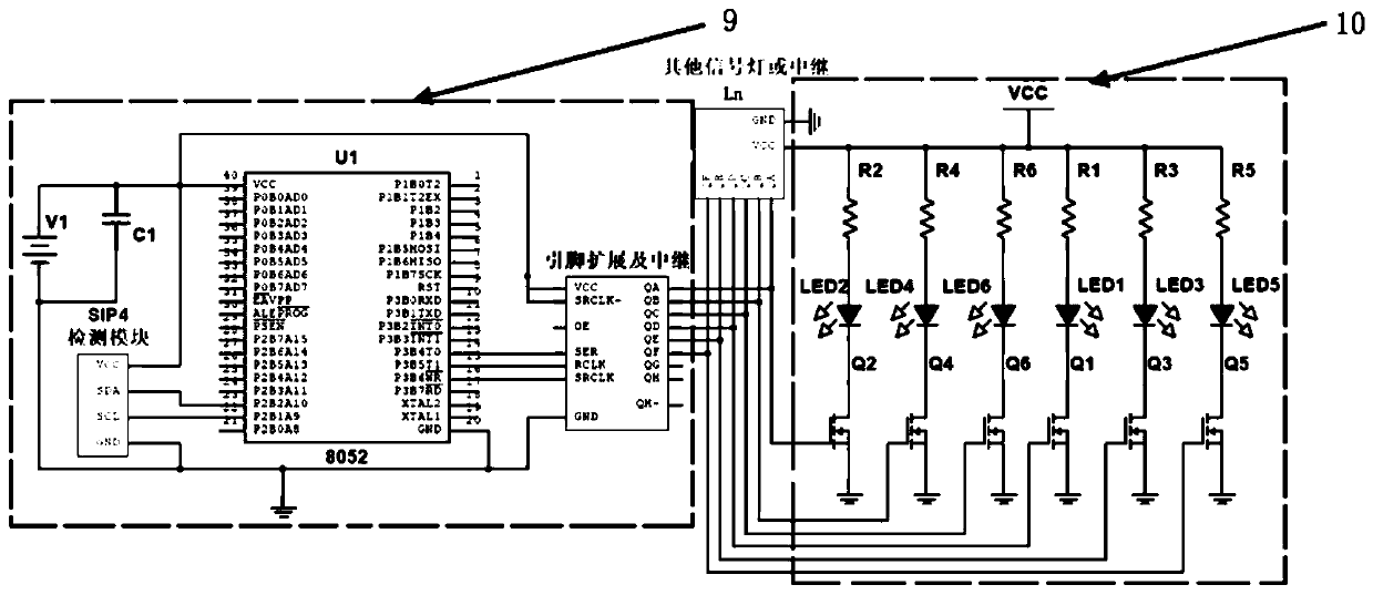
[0042] The present invention will be described in further detail below in conjunction with the accompanying drawings and specific embodiments. Such as figure 1 As shown, a dynamic road traffic signal control system includes a signal receiving and processing circuit 9 and a signal lamp control and energy circuit 10 .

[0043] The signal receiving and processing circuit 9 includes filter capacitor C1, detection module SIP4, pin extension and relay module and 52 single-chip microcomputers U1; filter capacitor C1 is connected in parallel to detection module SIP4, pin extension and relay module and 52 single-chip microcomputers U1 Both ends of the DC regulated power supply. Considering the line, the relay module for TV may be independent. The SDA and SCl pins of the detection module SIP4 are respectively connected with the P2B1 and P2B2 pins of the 52 single-chip microcomputer U1 to realize the output of the detection signal and the input of the control signal; the pin setting of...


PUM


Abstract

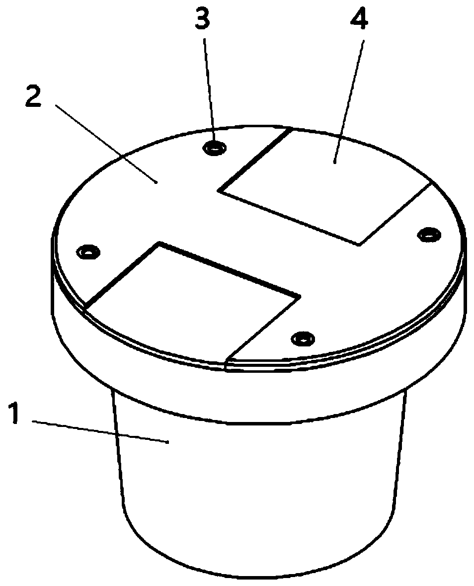
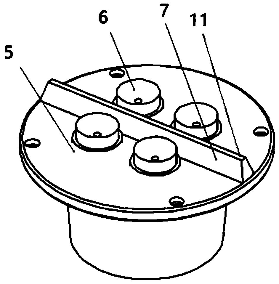
The invention discloses a dynamic road traffic signal control system and method. The system comprises a signal receiving and processing circuit and a signal lamp control and energy source circuit; thesignal receiving and processing circuit comprises a filter capacitor C1, a detection module SIP4, a pin extension and relay module and a 52 single chip microcomputer U1; the single lamp control and energy source circuit comprises multiple signal lamp branches, a light-emitting LED in each signal lamp branch is arranged in a buried signal lamp, and multiple buried signal lamps are buried in various lane lines; a light-emitting LED visible for the one-way coming vehicle is arranged at each of a coming side and a going side of each buried signal lamp; and the driving direction change of one lanecan be realized through three stages including an initial state, a conversion state and an end state. The system serves as the extension of the intersection traffic signal lamp at a road section, theprecision and the flexibility of the road resource distribution are obviously improved; the system is more flexible on the mounting distance and like parameters, and the arrangement way is designed and implemented in accordance with the road condition, thereby sufficiently meeting the demand and solving a specific problem.

Description

technical field [0001] The invention relates to the technical field of traffic signal control, in particular to a dynamic road traffic signal control system and method. Background technique [0002] With the development of the economy, the number of urban car ownership is increasing day by day. However, due to the late construction of most urban infrastructure in our country and the lack of foresight, the contradiction between cars and road space resources is growing day by day. The most obvious one is traffic jams. When the locomotive is in different working states (idling speed, acceleration, constant speed, deceleration), the impact on traffic emissions is different. When the vehicle is frequently in the deceleration or idling state, the emission will increase. Under traffic jams, cars will frequently be in a deceleration or idling state, so long-term traffic jams have caused an extreme waste of oil and natural gas resources and a huge increase in air pollutant emissions...

Claims


Application Information

Patent Timeline
Patent Type & Authority Applications(China)
IPC IPC(8): G08G1/08
CPCG08G1/08Y02B20/40
Inventor 张祖涛漆令飞刘苡辰张晨曦付峻峰戴睿鹏周启迪潘亚嘉
Owner SOUTHWEST JIAOTONG UNIV
Learn More