Composite purifier

A purifier and shell technology, applied in chemical instruments and methods, external electrostatic separators, electrode structures, etc., can solve the problems of high resistance, low maintenance and operating costs, and high operating and maintenance costs, and reduce the amount of entry into the side frame. opportunities, improve the effect of processing accuracy

Pending Publication Date: 2019-08-13
李焱
View PDF1 Cites 5 Cited by
  • Summary
  • Abstract
  • Description
  • Claims
  • Application Information

AI Technical Summary

Problems solved by technology

[0004] The purpose of the present invention is to provide a composite purifier for the technical problems of low purification efficiency, large resistance, high energy consumption, frequent cleaning, high operation and maintenance costs, fire hazards, and difficulty in removing gaseous pollutants in the prior art. The combination of the three areas, the charge area, and the dust collection area, and the flow of flue gas from the bottom to the top, organically combine the advantages of each area, complement and strengthen each other, and meet the simultaneous removal of solid, liquid, and gas in the flue gas. A variety of pollutant components, to achieve high purification efficiency and small resistance, low energy consumption, low maintenance and operation costs, long working life, reduce fire hazards and other beneficial effects

Method used


Image

  • Composite purifier
  • Composite purifier
  • Composite purifier

Examples


Embodiment 2

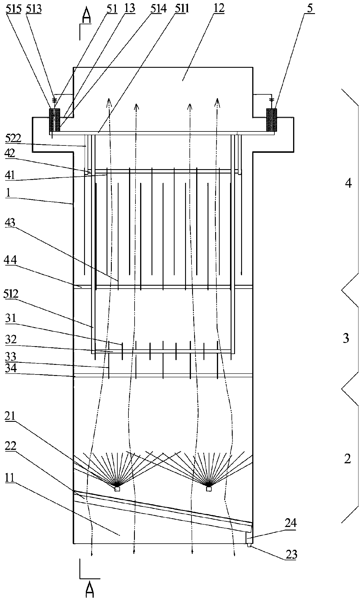
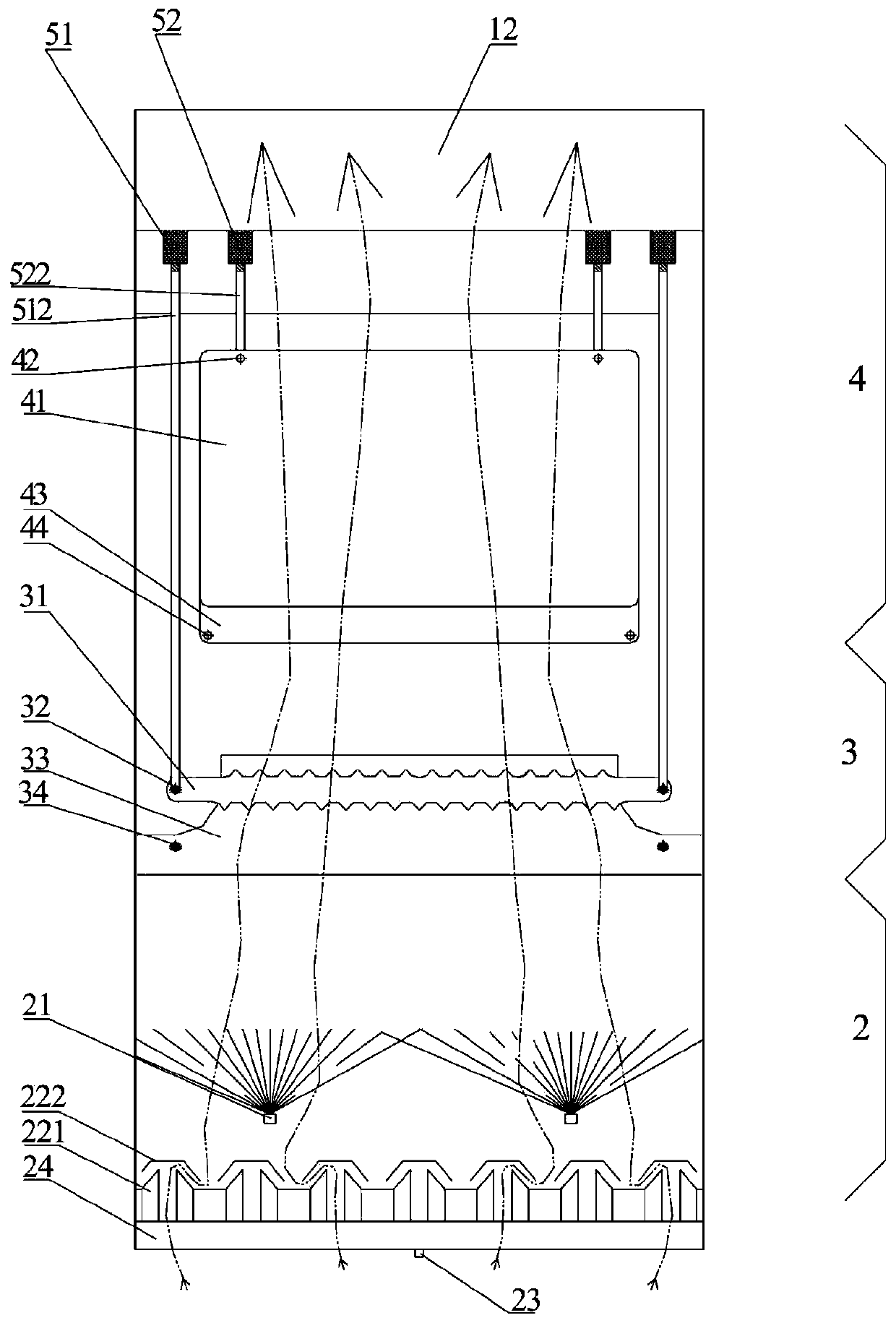
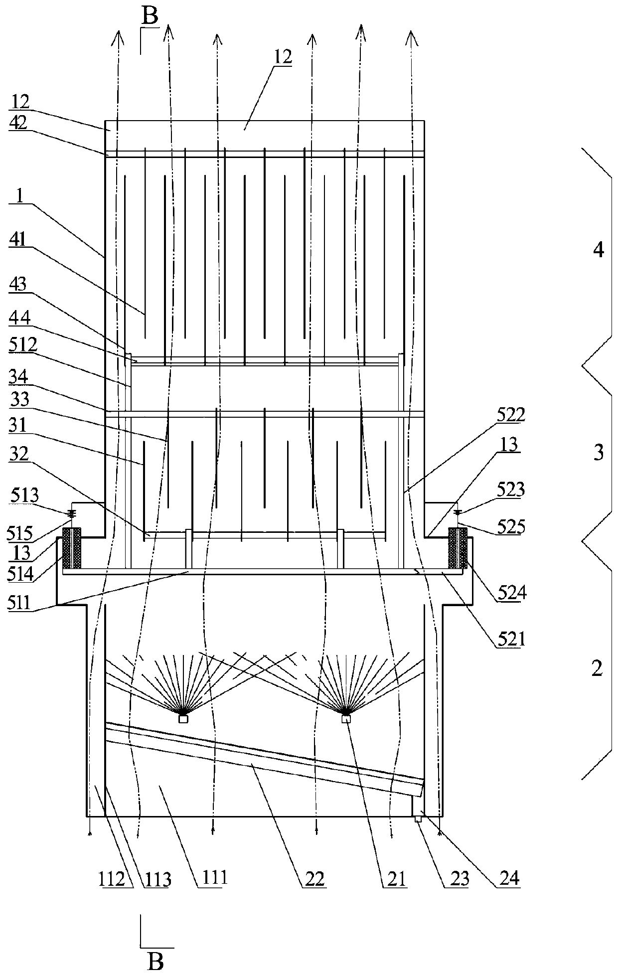
[0078] The use and working process of Embodiment 2: Under the action of negative pressure, the flue gas enters the casing 1 through the main air inlet 111 at the lower end of the casing 1 and the auxiliary air inlets 112 on both sides, and most of the flue gas enters the main air inlet 111. In the main air intake channel, the flue gas is washed by the water mist nozzle 21, part of the solid dust is wetted, the temperature of the flue gas decreases, and the gaseous oil molecules condense into a liquid state, which enters the charging area 3 with the airflow, and a small amount does not contain water mist The flue gas enters from the auxiliary air inlet 112 to prevent the water mist from splashing on the electrostatic power supply device 5 and the insulator, and also enters the charging area 3. By applying high-voltage static electricity to the charging area 3, the gas is charged at the corona electrode 31 and the discharge electrode plate 41. In the channel formed between them, ...


PUM


Abstract

The invention relates to a composite purifier, and the purifier comprises a shell provided with an air inlet and an air outlet. A water mist area is provided with a water mist nozzle and a baffle gridplate; a charge area is provided with a corona electrode and a charge area grounding electrode plate, wherein the corona electrode is connected with a corona electrode fixing rod, and the charge areagrounding electrode plate is connected with the charge area grounding electrode fixing rod; a discharge electrode plate of a dust collection area is connected with a discharge electrode fixing rod; adust collection area grounding electrode plate is connected with a dust collection area grounding electrode fixing rod; a dust collection area power supply device of an electrostatic power supply device is provided with a discharge electrode support, a charge area power supply device is provided with a corona electrode support, the discharge electrode support is connected with a discharge electrode fixing rod, and the corona electrode support is connected with the corona electrode fixing rod. Through combination of the water mist area, the charge area and the dust collection area and a bottom-in top-out flue gas flowing mode, the beneficial effects of high purification efficiency, low resistance, low energy consumption, low maintenance and operation cost, long service life, reduction of fire hazards and the like are achieved.

Description

technical field [0001] The invention relates to a flue gas purification treatment device, in particular to a composite purifier capable of producing composite purification. Background technique [0002] Regardless of cooking in the catering industry or industrial heat treatment, the flue gas contains solid dust particles, condensed liquid oil, and gaseous pollutants produced by oil cracking. There are many defects in a single purification treatment method, such as: the inertial separation method uses the inertia of dust particles in the airflow to separate, and the removal efficiency of particles with smaller particle sizes is low. For the flue gas produced by liquid condensate, such as oil fume, the ordinary filtration adsorption is easy to stick and clog, resulting in a large pressure drop and high energy consumption. The replacement of the filter material increases the operating cost. The liquid washing method has a higher purification efficiency, but for The purificatio...

Claims


Application Information

Patent Timeline
Patent Type & Authority Applications(China)
IPC IPC(8): B03C3/014B03C3/12B03C3/09B03C3/66B03C3/41B03C3/47B03C3/78B03C3/36
CPCB03C3/014B03C3/09B03C3/12B03C3/363B03C3/41B03C3/47B03C3/66B03C3/78
Inventor 李焱李跃瑞
Owner 李焱
Why Eureka
Try Eureka