Error-free current control method for switched reluctance motor

A technology of switched reluctance motor and current control, which is applied in the direction of current controller, AC motor control, control system, etc. It can solve the problems of poor performance of tracking current given value and large current fluctuation, etc., and achieve long control cycle and solution Effect of current fluctuation and reduction of switching loss

Active Publication Date: 2021-04-27
HEFEI UNIV OF TECH
View PDF2 Cites 0 Cited by
  • Summary
  • Abstract
  • Description
  • Claims
  • Application Information

AI Technical Summary

Problems solved by technology

[0011] In view of the shortcomings of the prior art, the purpose of the present invention is to provide an error-free switched reluctance motor current control method. When the control frequency is relatively low, the method comprehensively considers the advantages and disadvantages of current chopping control, and ensures that the switching Under the condition of reliable operation of the reluctance motor, the actual current of the motor can be adjusted and controlled accurately and effectively at low speed, medium speed and high speed, which overcomes the hysteresis control is a kind of fault-tolerant control, and there is an inevitable tracking error problem; solve The software current control method needs a certain amount of time to run, the disadvantages of large current fluctuations caused by long control cycles, and poor performance in tracking the current given value; at the same time, it weakens the potential current fluctuation problem caused by the delay of a sampling cycle in hysteresis control , Accurately control the motor current to track the reference current Improve the performance of the current actual value tracking the current reference value, thereby reducing the torque ripple of the switched reluctance motor

Method used


Image

  • Error-free current control method for switched reluctance motor
  • Error-free current control method for switched reluctance motor
  • Error-free current control method for switched reluctance motor

Examples


Embodiment Construction

[0050] In order to make the object, technical solution and advantages of the present invention clearer, the present invention will be further described in detail below in conjunction with the accompanying drawings. Apparently, the described embodiments are only part of the embodiments of the present invention. Based on the embodiments of the present invention, other embodiments obtained by those skilled in the art without creative work all belong to the protection scope of this patent.

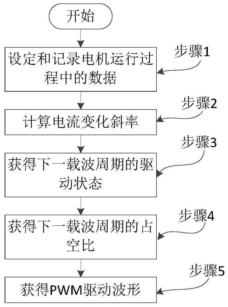
[0051] The example of the present invention provides an error-free switched reluctance motor current control method, which overcomes the shortcomings of the traditional current control method, controls the actual current to track the reference current without error, and improves the performance of the actual current value tracking the current reference value, thereby reducing Torque ripple in small switched reluctance motors.

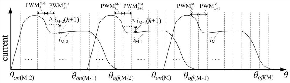
[0052] figure 2 Shown is a principle example diagram of the cont...


PUM


Abstract

The invention provides an error-free switched reluctance motor current control method. According to the parameters recorded when the motor is running, this method firstly obtains the current change slope of the next carrier cycle in any electrical cycle by calculation, and then accurately obtains the next carrier wave in any electrical cycle according to the difference between the actual current and the reference current. Cycle driving state, and accurately calculate the duty cycle required for the next carrier cycle in any electrical cycle. In a high-power electric drive system, this method realizes error-free current tracking under a limited switching frequency and improves the current tracking performance, thereby reducing the torque ripple output by the switched reluctance motor and improving the output performance of the motor.

Description

technical field [0001] The invention belongs to the switched reluctance motor control technology in the field of electrical engineering, and in particular relates to an error-free switched reluctance motor current control method. [0002] technical background [0003] Switched Reluctance Motor (SRM) is a new type of motor that has developed rapidly in the past ten years. It has large starting torque, wide speed range, flexible control, and can easily realize four-quadrant operation. It has strong regenerative Braking ability, with high efficiency in a wide range of speed and power, which is conducive to energy saving and consumption reduction; it can work at extremely high speeds; it can run with phase loss, and has strong fault tolerance. It has been widely used in aerospace, electric vehicles, oil field mining and household appliances and other fields. [0004] However, compared with traditional motors, SRM's doubly salient pole structure and switching power supply charact...

Claims


Application Information

Patent Timeline
Patent Type & Authority Patents(China)
IPC IPC(8): H02P6/28H02P25/098
CPCH02P6/28H02P25/098
Inventor 张兴杨晴晴马铭遥杨淑英
Owner HEFEI UNIV OF TECH
Why Eureka
Try Eureka