DPWM circuit with double-edge trigger hybrid structure and control method thereof

A hybrid structure and circuit technology, applied in electrical components, generation of electrical pulses, pulse duration/width modulation, etc., can solve problems such as difficulty in achieving high-frequency performance, complex structure, and single control method, and improve resource utilization. and circuit performance, reducing delay time deviation, and reducing the effect of response time

Active Publication Date: 2019-08-13
HEFEI UNIV OF TECH
View PDF9 Cites 10 Cited by
  • Summary
  • Abstract
  • Description
  • Claims
  • Application Information

AI Technical Summary

Problems solved by technology

[0002] Digital pulse width modulation (DPWM) has been a research hotspot in the field of digital switching power supplies in recent years. The shortcomings of traditional digital pulse width modulators and their control methods in terms of time resolution, dynamic response speed, power consumption, and resource occupation have always been the focus of digital technology. The main obstacle to the application in the field of switching power supply
Although a single DPWM module based on ordinary binary counter and comparator structure is simple to implement, the limit cycle oscillation caused by insufficient resolution will seriously affect the quality of the output voltage of the switching power converter
Due to its specific working mechanism, the DPWM based on the counter and comparator structure is difficult to achieve high frequency and relies too much on the performance of the clock generation circuit. The overall complexity and cost of the circuit are too high, which is not conducive to large-scale applications.
However, using the fine phase shift function of the high-performance clock management module to improve the time resolution of DPWM has the defect of long dynamic response time, which cannot meet the real-time requirements of high-performance switching converters.
[0003] At present, the time resolution of ordinary commercial digital pulse width modulators is low and the control method is single. The time resolution capability of mainstream products is between several nanoseconds and hundreds of nanoseconds, while high-precision pulse width modulation chips are expensive and complex in structure. , is not conducive to the promotion of the use of

Method used


Image

  • DPWM circuit with double-edge trigger hybrid structure and control method thereof
  • DPWM circuit with double-edge trigger hybrid structure and control method thereof
  • DPWM circuit with double-edge trigger hybrid structure and control method thereof

Examples


Embodiment Construction

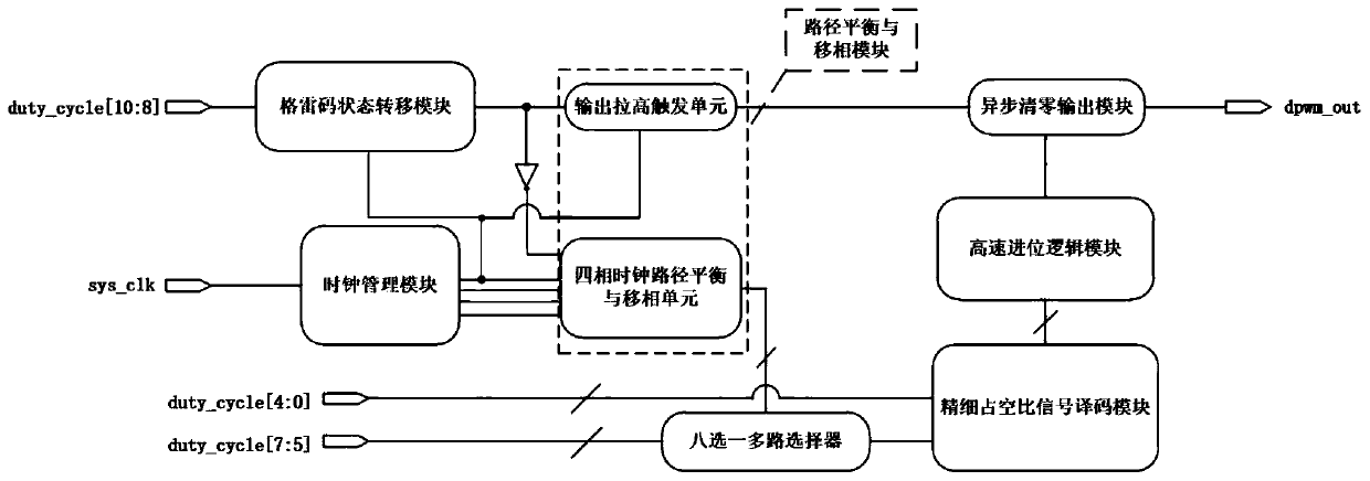
[0040]In this embodiment, an 11-bit DPWM circuit and its control method are taken as an example (but not limited to 11-bit), a DPWM circuit with a dual-edge trigger hybrid structure, including: a Gray code state transfer module, a path balance and phase shift module, a clock Management module, high-speed carry logic module, fine duty ratio signal decoding module, asynchronous clear output module;

[0041] The DPWM circuit divides the externally input duty cycle signal duty_cycle into three segments, including the first-level rough adjustment signal of the high h-bit duty cycle, the second-level coarse adjustment signal of the middle three bits, and the fine duty cycle signal of the low m-bit ;

[0042] like figure 1 As shown, in this embodiment, the input is the duty cycle signal duty_cycle, the duty_cycle[10:8] of the high 3-bit duty cycle first-level rough adjustment signal of the signal is input to the Gray code state transition module as the Gray code state transition mod...


PUM


Abstract

The invention discloses a DPWM circuit with a double-edge trigger hybrid structure and a control method thereof. The DPWM circuit comprises a Gray code state transition module, a clock management module, a path balance and phase shift module, a fine duty ratio signal decoding module, a high-speed carry logic module and an asynchronous clear output module. The path balancing and phase shifting module comprises an output pull-up trigger unit and a four-phase clock path balancing and phase shifting unit. According to the invention, the time resolution, the switching frequency and the dynamic response speed of the digital pulse width modulator can be improved, so that the output voltage ripples of the DC-DC converter and the required size of an off-chip passive device are reduced, and the response speed of the converter under the duty ratio fluctuation condition is further improved.

Description

technical field [0001] The invention relates to the field of power management chips, in particular to a pulse width modulation chip used in a switching power supply digital control loop and a control method thereof. Background technique [0002] Digital pulse width modulation (DPWM) has been a research hotspot in the field of digital switching power supplies in recent years. The shortcomings of traditional digital pulse width modulators and their control methods in terms of time resolution, dynamic response speed, power consumption, and resource occupation have always been the focus of digital technology. The main obstacle to the application in the field of switching power supply. Although a single DPWM module based on ordinary binary counter and comparator structure is simple to implement, the limit cycle oscillation caused by insufficient resolution will seriously affect the quality of the output voltage of the switching power converter. Due to its specific working mechan...

Claims


Application Information

Patent Timeline
Patent Type & Authority Applications(China)
IPC IPC(8): H03K3/017H03K5/133H03K5/135H03K7/08
CPCH03K3/017H03K5/133H03K5/135H03K7/08
Inventor 程心李斌张云峰
Owner HEFEI UNIV OF TECH
Why Eureka
Try Eureka