Wireless communication device

A wireless communication device and channel technology, applied in the field of ultrasonic transmission, can solve problems such as unusability, reduce safety factor, increase maintenance cost, etc., and achieve the effects of rapid disassembly, cost reduction, and installation process reduction.

Pending Publication Date: 2019-08-13
IOASONIC SU ZHOU TECH CO LTD
View PDF0 Cites 1 Cited by
  • Summary
  • Abstract
  • Description
  • Claims
  • Application Information

AI Technical Summary

Problems solved by technology

[0002] In some industrial or military applications, it is necessary to transmit information through the enclosure of sealed metal cabins or containers (such as spacecraft, hyperbaric oxygen chambers, nuclear reactors, etc.), which are limited by the shielding effect of the metal enclosures of these cabins and containers. Traditional wireless communication technologies that use electromagnetic waves as information carriers cannot be used
At present, the most common and direct method is to punch holes in the outer shell of these metal cabins or containers for wired communication, which will destroy the structural integrity of the metal shell, thereby inevitably reducing its safety factor and increasing maintenance costs.

Method used


Image

  • Wireless communication device
  • Wireless communication device
  • Wireless communication device

Examples


Embodiment 1

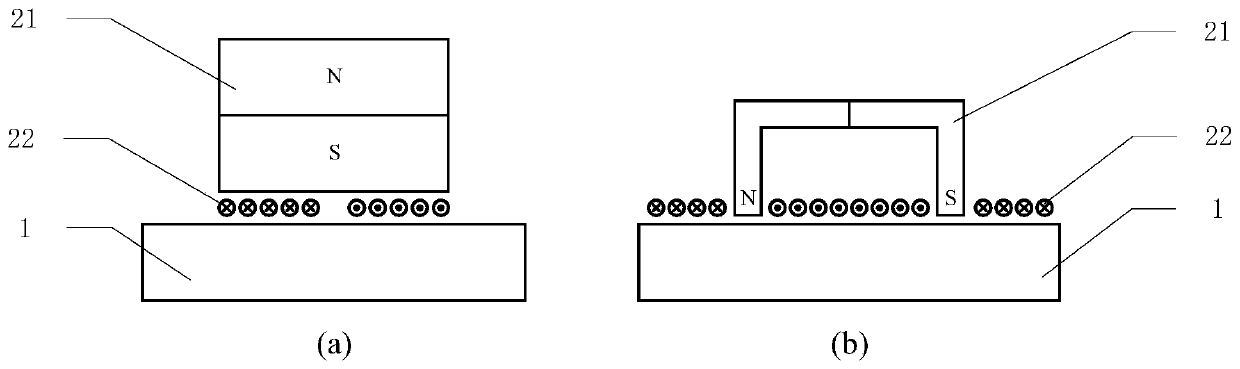
[0026] See figure 1 and figure 2 , a wireless communication device, including at least one ultrasonic channel, each of which includes a first transducer 2 arranged on one side of a metal barrier 1 and a first signal processing circuit connected to the first transducer 2 , the second transducer 3 arranged on the other side of the metal barrier and the second signal processing circuit connected to the second transducer 3 . Both the first transducer 2 and the second transducer 3 use electromagnetic sound transducers, and the transducers are in direct contact with the metal barrier, or do not contact so that there is an air gap between the transducer and the metal barrier, correspondingly Compared with the system using piezoelectric transducers, the use of electromagnetic acoustic transducers does not require good coupling between the transducer and the metal barrier, reducing the installation process, and at the same time realizing quick disassembly and reducing costs. Describ...

Embodiment 2

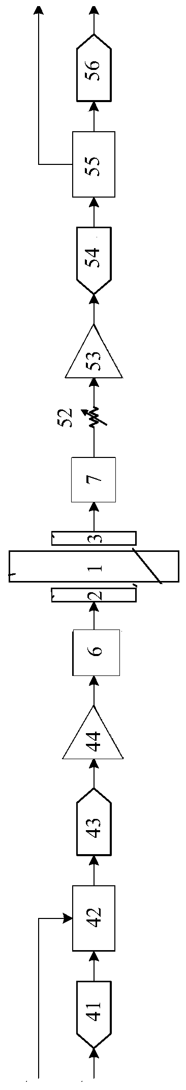
[0034] See image 3 , the first signal processing circuit includes a transmitting-end signal processing circuit, and the second signal processing circuit includes a receiving-end signal processing circuit.

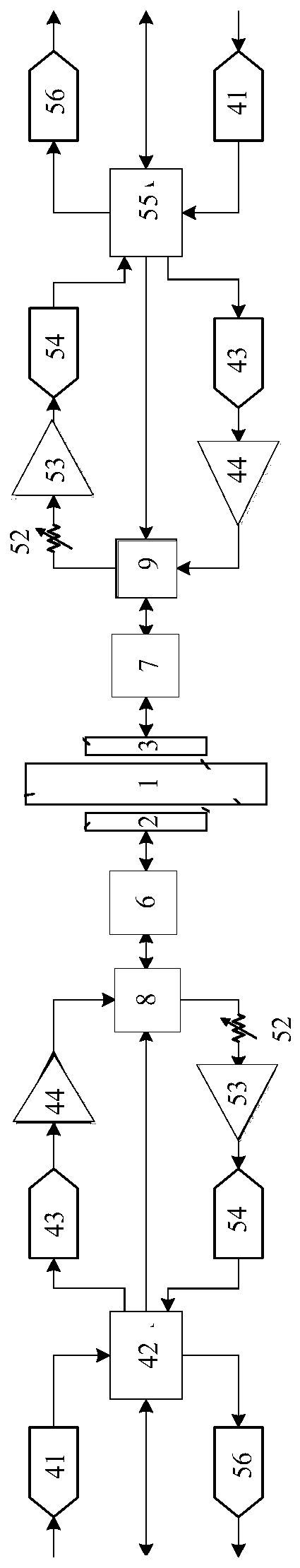
[0035] Each of the ultrasonic channels includes a first analog / digital converter 41, a first field programmable gate array 42, a first digital / analog converter 43, a power amplifier 44, a first digital / digital converter 43, a power amplifier 44, and a sequentially electrically connected one side of the metal barrier. An impedance matching circuit 6 and the first transducer 2, the second transducer 3, the second impedance matching circuit 7, the attenuator 52, the low noise amplifier 53, the second The analog / digital converter 54, the second field programmable gate array 55 and the second digital / analog converter 56, after the signal source is input to the first ADC41 or the first FPGA42, the first FPGA41 performs encoding, modulation, filtering and other processing, and T...


PUM


Abstract

The invention discloses a wireless communication device. The wireless communication device comprises at least one ultrasonic channel, and each ultrasonic channel comprises a first transducer arrangedon one side of a metal barrier, a first signal processing circuit connected with the first transducer, a second transducer arranged on the other side of the metal barrier and a second signal processing circuit connected with the second transducer. According to the wireless communication device, ultrasonic waves which are not in the auditory range of human ears are adopted as information conversionmedia to penetrate through the metal barrier to be used for information transmission, and high-speed and error-free information transmission is achieved under the condition that the integrity of themetal barrier is not damaged. According to the wireless communication device, the electromagnetic acoustic transducer is adopted, non-contact ultrasonic transmitting and receiving with a metal barrierare achieved, the installation procedures of the wireless communication device are reduced, meanwhile, rapid disassembling is achieved, and the cost is reduced.

Description

technical field [0001] The invention relates to the field of ultrasonic transmission, in particular to a wireless communication device. Background technique [0002] In some industrial or military applications, it is necessary to transmit information through the enclosure of sealed metal cabins or containers (such as spacecraft, hyperbaric oxygen chambers, nuclear reactors, etc.), which are limited by the shielding effect of the metal enclosures of these cabins and containers. Due to limitations, traditional wireless communication technologies that use electromagnetic waves as information carriers cannot be used. The most common and direct method at present is to punch holes in the shells of these metal cabins or containers for wired communication, which destroys the structural integrity of the metal shells, thereby inevitably reducing its safety factor and increasing maintenance costs. Contents of the invention [0003] The purpose of the present invention is to provide ...

Claims


Application Information

Patent Timeline
Patent Type & Authority Applications(China)
IPC IPC(8): H04B11/00H04B1/00H04R13/00
CPCH04B1/0003H04B11/00H04R13/00
Inventor 杨恒旭
Owner IOASONIC SU ZHOU TECH CO LTD
Why Eureka
Try Eureka