Intractable heart failure left ventricular function auxiliary device

A technology of heart failure and auxiliary devices, applied in the field of medical devices, can solve the problems of increasing the risk of patients tolerating surgery, dilation of blood vessels such as the aorta, and increasing the chance of infection

Pending Publication Date: 2019-08-16
THE AFFILIATED HOSPITAL OF QINGDAO UNIV
View PDF0 Cites 2 Cited by
  • Summary
  • Abstract
  • Description
  • Claims
  • Application Information

AI Technical Summary

Problems solved by technology

2. The Impella system is a constant-speed operation system that requires arterial incision and implantation. Although it is easy to operate, it can be used for left or right ventricular assisted circulation; but it also needs to preserve the left ventricular function, so the patient's tolerance is poor. Moreover, the device cannot simulate the rhythmic pulsation of human blood flow, so it will cause the continuous expansion of blood vessels such as the aorta, causing the patient's blood pressure to rise, causing headaches and other discomfort
3. Systems pLVAD, the pump is outside the body and needs to be implanted through the chest. The pump tube is connected to the device through the skin, and the pump with different power and cardiac output can be replaced according to the needs without re-replacing the catheter system; but it significantly increases the patient's tolerance to surgery risk, increased chance of infection
[0003] The above-mentioned devices have their own advantages and disadvantages. The main disadvantage is that the left ventricle can be completely replaced, or the function of the systolic pump ...

Method used


Image

  • Intractable heart failure left ventricular function auxiliary device

Examples


Embodiment Construction

[0012] The present invention will be described in detail below in combination with specific embodiments.

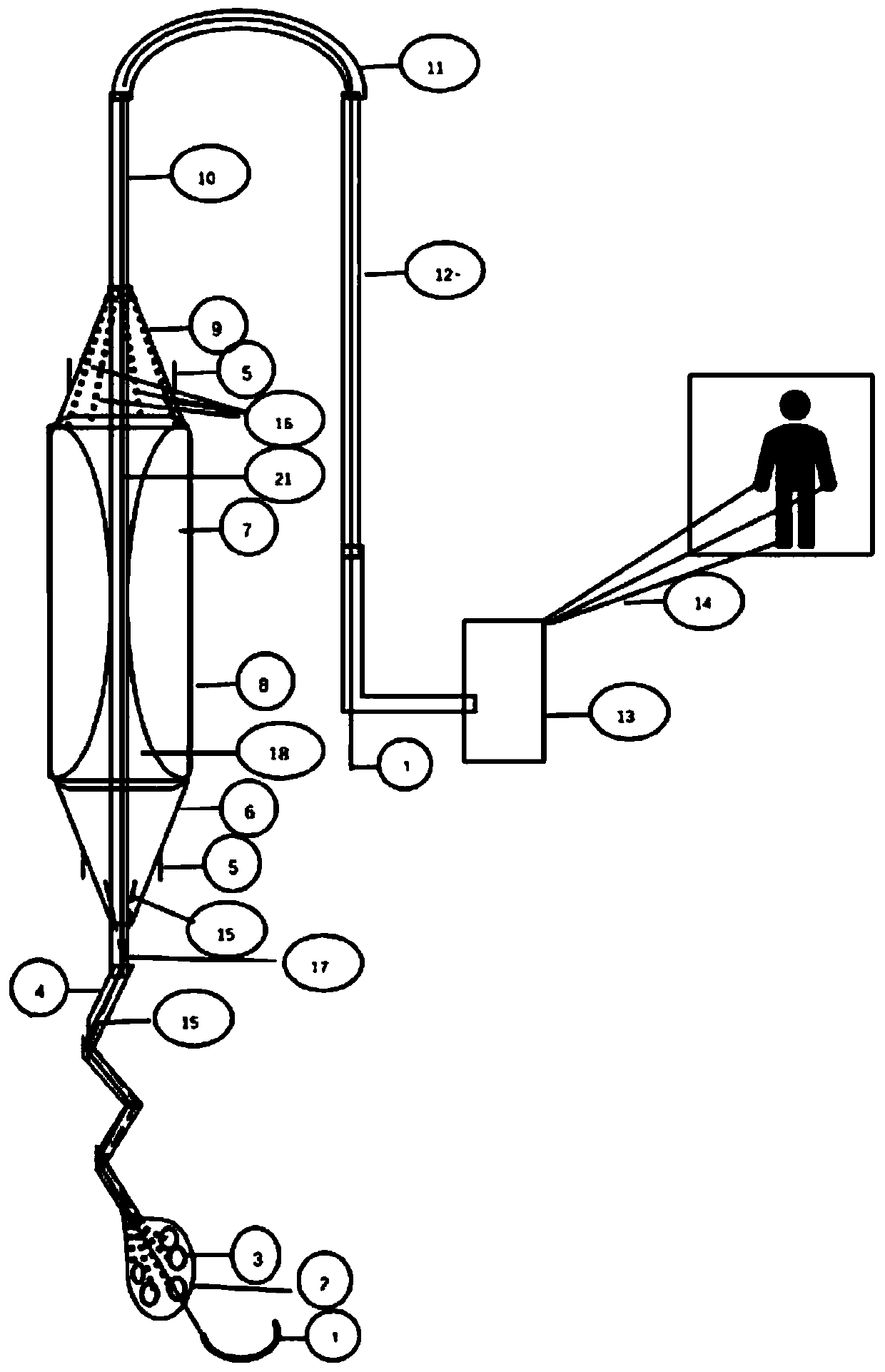
[0013] The inventive device such as figure 1 As shown, the indoor section is divided into two parts: a spiral suction pipe 4 and a drop-shaped suction head 2. There are multiple suction pipes and cyst cavity tunnels 15 inside the suction head. Leading to the tapered cavity 6 at the proximal end, a one-way valve is designed at the place where the pipeline communicates with the cavity 18, and communicates with the inner cavity of the airbag through the one-way valve 5. After the blood is inhaled, it is guaranteed that the blood will not return during the inflation stage of the airbag. Flow, and through the sac cavity check valve 5 will be discharged into the aorta. The length of the straw across the valve segment 17 is 30-50cm. It is designed in a flat leaf shape. The inside is a single channel connected to the drop-shaped suction head 2. The distal end communicates with t...


PUM

PropertyMeasurementUnit
Lengthaaaaaaaaaa

Abstract

The invention discloses an intractable heart failure left ventricular function auxiliary device. Various straws and cavity tunnels are designed in a suction head, outer sucking holes are formed in thelower wall and the outer side of the suction head, a straw is led to a proximal end conical cavity inwards, a one-way valve is designed at a position communicated with the cavity in a pipeline of thestraw, the straw is communicated with an inner cavity of an air bag through the one-way valve, a single channel is connected with the drop-shaped suction head in a straw valve crossing section, a distal end is communicated with an air bag chamber, four one-way valves are arranged on the outer wall of the trapezoid side surface of a capsule and communicated with an inner cavity of the air bag chamber through channels, conical upper end is connected with an air-space tunnel through a trachea, branch tracheae pass the air bag chamber downwards and are opened on the inner side of the wall of theair bag and converged into a main trachea upwards, the main trachea is communicated with outside thought an artery, and the lower end of a guide wire is communicated with the drop-shaped suction head.The device has the advantages that the device can continuously work under the condition of left ventricular function loss, and time is bought for clinical rescue or heart transplantation.

Description

technical field [0001] The invention belongs to the technical field of medical devices and relates to a left ventricular function assisting device for refractory heart failure. Background technique [0002] Acute heart failure: The main manifestations are decreased left ventricular function, that is, decreased left ventricular pumping function, cardiac pump insufficiency, reduced work, left ventricular congestion, resulting in pulmonary congestion and dyspnea in patients. The device can assist the left ventricle to work, reduce the congestion in the lungs, thereby reducing the work of the left ventricle, recovering the pump function of the left ventricle, reducing pulmonary congestion and pulmonary edema caused by acute left ventricular insufficiency, and relieving symptoms such as dyspnea and wheezing. , to help patients successfully pass through acute myocardial infarction, acute left ventricular insufficiency and high-risk periods caused by other reasons, and achieve smoo...

Claims


Application Information

Patent Timeline
IPC IPC(8): A61M1/10A61M1/12
CPCA61M2230/04A61M60/00A61M60/135A61M60/148A61M60/268A61M60/50A61M60/857A61M2230/005
Inventor 许丰强胡龙刚安毅郭俊杰
Owner THE AFFILIATED HOSPITAL OF QINGDAO UNIV
Why Eureka
Try Eureka