Transformation method applicable to spandrel structure of two-way curved arch bridge

A technology for double-curved arch bridges and arch bridges, which is applied in the renovation of buildings on arches and in the field of renovation of buildings on arches with cast-in-place concrete with steel bottom formwork. High requirements for mechanical equipment and other issues, to achieve the effect of improving driving comfort and durability, shortening the construction period, and simple and orderly construction steps

Inactive Publication Date: 2019-08-16
中铁桥隧技术有限公司
View PDF9 Cites 4 Cited by
  • Summary
  • Abstract
  • Description
  • Claims
  • Application Information

AI Technical Summary

Problems solved by technology

[0005] (1) Transverse joints and water seepage problems commonly exist in simply supported slabs; on continuous slabs, due to the limitation of slab thickness and the unreasonable ratio of side spans to mid-spans, etc., the problem of negative bending moment cracking at the top of piers commonly exists;
[0006] (2) Under the impact of vehicle load or braking, the roadway slab bears a horizontal force, which cannot be effectively transmitted to the arch ring, resulting in a sliding tendency of the roadway slab;
[0007] (3) For continuous slabs, prefabrication is usually used, and wet joints are poured after hoisting for continuous construction, which requires high construction machinery and equipment; the construction period is long, and the integrity of continuous slabs is poor

Method used


Image

  • Transformation method applicable to spandrel structure of two-way curved arch bridge
  • Transformation method applicable to spandrel structure of two-way curved arch bridge

Examples


Embodiment Construction

[0031] The following describes the present invention in detail with reference to the drawings and specific embodiments.

[0032] A reconstruction method suitable for buildings on double-curved arch bridges, including the following steps:

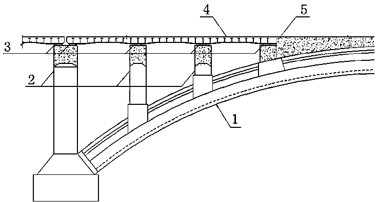
[0033] S1. The double-curved arch bridge after removing the arch on the building, such as figure 1 As shown, the main arch ring part of the double-curved arch bridge has a solid web section of the vault and an open web section of the arch bridge at both ends;

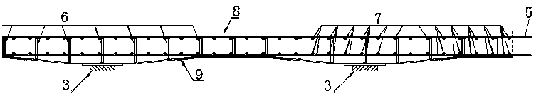
[0034] S2. The transverse partition wall connecting the open web section of the high arch bridge and the solid web section of the vault, the top surface is flush or flat;

[0035] S3. Place a PTFE slide support on the top of the transverse partition wall;

[0036] S4. Several steel bottom molds are hoisted to the support in a continuous plate shape, a number of shear nails welded on the inner side of the steel bottom mold, and the shear nails are welded with the laid double-layer steel mesh as ...


PUM


Abstract

The invention discloses a transformation method applicable to a spandrel structure of a two-way curved arch bridge. The transformation method comprises the steps that after the spandrel structure is removed, the two-way curved arch bridge is provided with an arch bridge open-spandrel segment and an arch crown filled-spandrel segment, a cross partition wall of the arch bridge open-spandrel segmentand a cross partition wall of the arch crown filled-spandrel segment are subjected to jointing, supporting seats are placed on the cross partition walls, steel bottom formworks are hoisted onto the supporting seats, a plurality of shear studs are welded onto the inner sides of the steel bottom formworks, the shear studs and a laid double-layer reinforcement mesh are welded into the whole, and theends of the shear studs are fixedly connected with the arch crown filled-spandrel segment through rebars; concrete is poured at the arch crown filled-spandrel segment; and concrete carriageway platesare overall poured on the whole bridge at a time. According to the transformation method, the bearing ability of the carriageway plates is effectively improved, the crack resistance of the carriagewayplates is improved, thus traveling comfort and durability are improved, connecting between the carriageway plates and a main arch ring is improved, thus the horizontal load on a bridge deck is effectively transmitted to the main arch ring, the construction steps are easy, convenient and orderly, and the transformation method has the quite high practicality and wide applicability.

Description

Technical field [0001] The invention relates to a method for reconstructing a building on an arch, in particular to a method for reconstructing a building on a double-curved arch bridge with a steel bottom mold cast-in-place concrete, and belongs to the technical field of bridge reconstruction. Background technique [0002] The appearance of double-curved arch bridges has been around for more than 60 years. Because of its design and construction methods of breaking up into parts and collecting and distributing are very suitable for China's national conditions, it has been constructed on a large scale. However, it was found in operation that the bridge type had poor integrity, low bearing capacity, and durability problems such as water seepage in the arch. Many double-curved arch bridges are even facing demolition. Therefore, a large number of double-curved arch bridges have been reinforced or remodeled. [0003] Reconstruction of the arch-on-arch is the most commonly used renovat...

Claims


Application Information

Patent Timeline
Patent Type & Authority Applications(China)
IPC IPC(8): E01D22/00E01D4/00
CPCE01D4/00E01D22/00
Inventor 崔海陆勤丰刘华孙英杰张军雷耿东升付一小
Owner 中铁桥隧技术有限公司
Why Eureka
Try Eureka