Infrared touch glass mounting structure, touch precision adjusting method and application

A technology of infrared touch and installation structure, which is applied in the direction of instruments, electrical digital data processing, and input/output process of data processing, etc. It can solve the problems of increasing the thickness of the main frame, the lamp head is prone to fog and dust, and the touch is slow.

Pending Publication Date: 2019-08-16
OPTON (SHUNCHANG) OPTICS CO LTD
View PDF1 Cites 5 Cited by
  • Summary
  • Abstract
  • Description
  • Claims
  • Application Information

AI Technical Summary

Problems solved by technology

[0003] 1. During the combination process of the surrounding frame, there will be a difference in combination twist angle, and the tightness of the printed circuit board of the infrared light bar will also produce a difference in accuracy when inserted into the aluminum frame groove. Too tight will make it difficult to insert, and too loose will cause the screen to vibrate. The infrared signal jitters;
[0004] 2. Before the external composite aluminum frame is not embedded in the glass of the touch screen, hands cannot touch it, and cannot know or adjust the touch effect
However, it is difficult to adjust after the touch screen glass is embedded because the infrared light bar has been inserted into the combined external aluminum frame, which makes it difficult and time-consuming to adjust the touch effect of the infrared touch screen during mass production and maintenance, and every time The effect of one touch is not the same, and the assembly consistency is poor;
[0005] 3. The plug-in structure of the light-transmitting dust-proof strip and the frame also leads to poor sealing of the light-transmitting dust-proof strip, and it is easy to leak water and dust, thus causing the lamp head of the infrared emitting / receiving tube to be easily fogged and dusty, and the printed circuit board is easily short-circuited when it is damp. In addition, the presence of the bottom edge of the infrared filter slot also increases the thickness of the main frame. The higher the vertical height between the horizontal optical axis and the touch glass, the worse the touch sensitivity and inaccuracy. Hysteresis
[0006] Since the optical axes of the emitting light path and receiving light path of the infrared pair tubes currently on the market are difficult to be on the plane horizontal optical axis, and the height from the touch glass is also higher than the vertical height distance of the capacitive screen, resulting in tactile or fast Or slow, the touch is not smooth; and when the capacitive touch touches any surface of the capacitive touch glass, the distance between the finger and the capacitive sensing film line attached to the glass is the same, and the response time of the touch sensing is fast and unanimous
Therefore, although the traditional infrared touch module is cheaper than the capacitive touch screen, there is still a big gap between the sensitivity and the capacitive touch screen.

Method used


Image

  • Infrared touch glass mounting structure, touch precision adjusting method and application
  • Infrared touch glass mounting structure, touch precision adjusting method and application
  • Infrared touch glass mounting structure, touch precision adjusting method and application

Examples


Embodiment 1

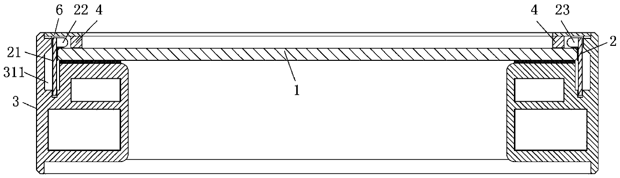
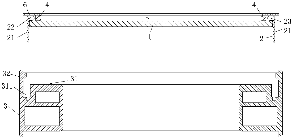
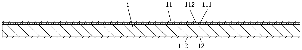
[0037] Such as Figure 1 to Figure 4 As shown, an infrared touch glass installation structure includes a glass reference plate 1, an infrared touch module 2 and a screen support frame 3, and the infrared touch module 2 includes The circuit board 21 of each circuit board 21 is correspondingly welded with one of the infrared tubes on the edge of each circuit board, and the infrared emitting tube 22 and the infrared receiving tube 23 between the opposite circuit boards correspond one by one; the back side 12 of the glass reference plate 1 is Warped surface, the front side 11 of the glass reference plate is provided with an anti-glare layer 111 made by sandblasting and etching, and the surface of the warped surface and the anti-glare layer has a compressive stress layer 112 formed by chemical strengthening; the infrared pair tubes are all made of solid ultraviolet flexible The glue is pasted around the front of the glass reference plate 1 and forms an infrared touch glass with the...

Embodiment 2

[0045] Such as figure 1 , Figure 5 with Image 6 As shown, a high-sensitivity fully sealed infrared touch all-in-one machine includes an infrared touch glass 10, a screen support frame 20, a liquid crystal panel 30, and a backlight module 40. The infrared touch glass 10 and the screen support frame 20 The structure is as described in Embodiment 1, the liquid crystal panel 30 is pasted on the back of the glass reference plate 1, the circuit board 21 of the infrared touch glass 10 is inserted into the sinker 202, and the glass reference plate 1 is placed on the screen installation platform 201 and fixed with the screen mounting table 201; the opposite sides of the infrared emitting tube 22 and the infrared receiving tube 23 are equipped with infrared filter strips 50, the bottom of the infrared filter strips 50 and the glass reference plate 101 The surface is bonded and fixed, and an opaque cover plate 60 is respectively installed above the infrared emitting tube 22 and the i...

Embodiment 3

[0048] Such as figure 1 with Figure 7 As shown, a high-sensitivity fully sealed infrared touch all-in-one machine includes an infrared touch screen 10, a screen support frame 20, a liquid crystal panel 30, and a backlight module 40. The infrared touch screen 10 and the screen support frame 20 The structure is as described in Embodiment 1. The circuit board 21 of the infrared touch screen 10 is inserted into the sinker 202, and the glass reference plate 101 is placed on the screen installation platform 201 and fixed with the screen installation platform 201; The opposite sides of the infrared emitting tube 22 and the infrared receiving tube 23 are equipped with an infrared filter strip 50, the bottom of the infrared filtering strip 50 is bonded and fixed to the surface of the glass reference plate 101, and the infrared emitting tube 22 and the infrared receiving tube 23 Opaque cover plates 60 are respectively installed on the top of the backlight module 40; the liquid crystal...


PUM


Abstract

The invention discloses an infrared touch glass mounting structure. An infrared transmitting tube and an infrared receiving tube are respectively adhered to the periphery of the front surface of the glass reference plate; the touch effect can be adjusted during pasting; after the warping surface of the glass reference plate is measured, sand blasting etching processing is performed on the back surface of the warped surface, and finally chemical strengthening is performed, the warping degree of the glass can be corrected; the heights of all the infrared transmitting tubes and all the infrared receiving tubes of the infrared geminate transistors on the glass reference plane are further ensured to be the same; the infrared emission light path and the infrared receiving light path are both located in an infrared light channel of the infrared filtering strip, so that the touch height of the infrared touch control glass is equal to the radius of the infrared emission tube and the radius of the infrared receiving tube, and the touch control sensitivity is improved; the infrared touch screen and the back plate of the backlight module are attached to the screen supporting frame, and full sealing of the infrared touch liquid crystal display module is achieved.

Description

technical field [0001] The invention relates to the field of infrared touch display devices, in particular to a high-precision infrared touch screen installation structure, an infrared touch glass installation structure, a touch precision adjustment method and its application. Background technique [0002] The installation structure of the infrared touch components in the traditional infrared touch all-in-one machine is shown in the frame structure of an infrared touch display device disclosed in Chinese Patent No. 201020679896.8. The infrared emitting / receiving tube group is vertically welded and fixed on the corresponding printed circuit On the board, the frame is provided with an opening channel for emitting and receiving infrared rays, the printed circuit board is perpendicular to the opening direction of the opening channel of the frame and embedded in the aluminum frame groove around the periphery, and each emission of the infrared emitting / receiving tube group The tub...

Claims


Application Information

Patent Timeline
Patent Type & Authority Applications(China)
IPC IPC(8): G06F3/042
CPCG06F3/042
Inventor 卢璋余启明吴章祥胡东伟黄双枝
Owner OPTON (SHUNCHANG) OPTICS CO LTD
Why Eureka
Try Eureka