
Thermal power plant 0 class load power supply system and control method

A technology for power supply systems and thermal power plants, applied in electrical components, circuit devices, AC network circuits, etc., can solve the problems of complex power distribution systems and wiring lines, general operating reliability, and large fluctuations in power quality, and achieve work efficiency. Fast switching speed, good for startup, simple and reliable wiring

Pending Publication Date: 2019-08-16
NORTHWEST ELECTRIC POWER DESIGN INST OF CHINA POWER ENG CONSULTING GROUP
View PDF0 Cites 1 Cited by
  • Summary
  • Abstract
  • Description
  • Claims
  • Application Information

AI Technical Summary

Problems solved by technology

[0005] In a conventional thermal power plant, a large-scale AC uninterruptible power supply system, namely UPS, is used as an OI load power supply; a 220V DC lead-acid storage battery or a nickel-hydrogen battery pack is used as an OII load power supply; a diesel generator set is used as an OIII load power supply, and the power supply type Complex; at the same time, thermal power plants have a large number of O-load power supply system equipment, complex power distribution systems and wiring lines, occupy a large space, have many auxiliary equipment, high system cost, heavy maintenance workload, and a considerable amount of gaseous environmental pollutants Emissions and noise pollution, the overall reliability of operation is average, and the power quality fluctuates greatly

Method used


Image

  • Thermal power plant 0 class load power supply system and control method

Examples


Embodiment Construction

[0033] In order to enable those skilled in the art to better understand the solutions of the present invention, the technical solutions in the embodiments of the present invention will be described clearly and completely with reference to the accompanying drawings in the embodiments of the present invention. Obviously, the described embodiments are only It is a part of the embodiments of the present invention, not all the embodiments. Based on the embodiments of the present invention, all other embodiments obtained by those of ordinary skill in the art without creative work shall fall within the protection scope of the present invention.

[0034] It should be noted that the terms "first" and "second" in the specification and claims of the present invention and the above-mentioned drawings are used to distinguish similar objects, and not necessarily used to describe a specific sequence or sequence. It should be understood that the data used in this way can be interchanged under ap...


PUM


Abstract

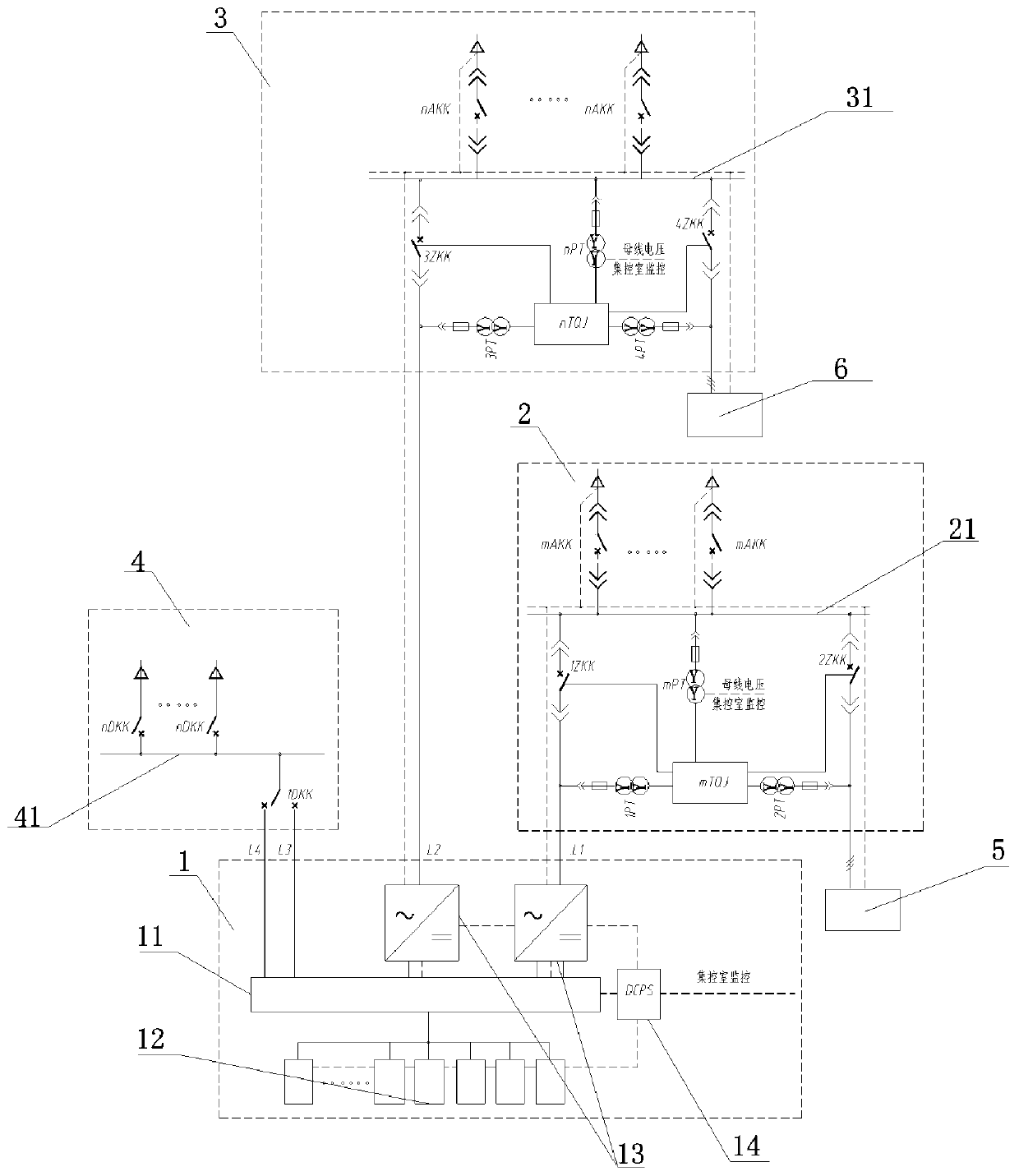
The invention discloses a thermal power plant 0 class load power supply system and control method. The system comprises an energy storage device, an AC uninterrupted power load low-voltage power distribution device, an AC security load low-voltage power distribution device, and a DC security load DC power distribution device. The AC uninterrupted power load low-voltage power distribution device, the AC security load low-voltage power distribution device and the DC security load DC power distribution device are internally provided with an AC uninterrupted power load bus, an AC security load busand a DC security load bus respectively. The energy storage device is connected to the AC uninterrupted power load bus, the AC security load bus and the DC security load bus through a first switch, asecond switch and a third switch. The AC uninterrupted power load bus is also connected to a first power supply for a thermal power plant power through a fourth switch, and the AC security load bus is also connected to a second power supply for the thermal power plant power through a fifth switch. The system is intensively streamlined, compared with a conventional method, fully static equipment improves the reliability of a 0 class load power supply of the thermal power plant, the power supply quality is improved, and pollutant emissions are reduced.

Description

Technical field [0001] The invention belongs to the field of power supply and distribution of thermal power generating sets, and relates to a power supply system and a control method for class O load of thermal power plants. Background technique [0002] Class O auxiliary power loads of power plants include Class OI, Class OII and Class OIII. OI category is AC non-stop power load, OII category is DC security load, OIII category is AC security load. The specific load operation characteristics and power supply requirements are as follows: [0003] OI load refers to the load that needs continuous power supply during the operation of the generator set and boiler, and during the shutdown of the generator set and boiler (including accidental shutdown), and even for a period of time after the shutdown, which is called non-stop power load; including The computer control system, thermal protection device, automatic control and adjustment device, electric actuator and communication device ...

Claims


Application Information

Patent Timeline
IPC IPC(8): H02J3/00H02J3/32
CPCH02J3/32H02J3/0073
Inventor 王立康刘学军朱蕊莉鲁齐樊涛李诚魏燕曹仑苏晓
Owner NORTHWEST ELECTRIC POWER DESIGN INST OF CHINA POWER ENG CONSULTING GROUP
Learn More