Automatic cutting equipment of integrated circuit tube shell lead frame

A technology of integrated circuits and shell leads, applied in the field of automatic cutting equipment, can solve the problems of frequent replacement, fast wear of plastic positioning blocks, long working hours, etc., and achieve the effect of reducing operating labor intensity, improving mold life, and low technical requirements

Inactive Publication Date: 2019-08-20
刘玉琦
View PDF8 Cites 3 Cited by
  • Summary
  • Abstract
  • Description
  • Claims
  • Application Information

AI Technical Summary

Problems solved by technology

The above-mentioned method of cutting off the frame is the production method commonly used by enterprises at present. For a long time, the following defects have plagued the producers: (1) It is difficult to ensure the length tolerance by manual positioning to ensure the size. Proficiency, improper placement and skewed placement will cause the length of the lead to be out of tolerance, especially the skewed placement will directly lead to product scrapping, and the scrapping rate of novice operations is higher; (2) The length of the cut lead due to unreliable positioning The consistency is poor, which increases the difficulty of the subsequent process and affects the product quality; (3), the original rigidity of the lead wire is lost after cutting off the frame at one end, and it is easy to cause the lead wire to be deformed to varying degrees when holding the U-turn, which has a great adverse effect on the implementation of the next process; (4) The working hours are long, and the operator is prone to fatigue and make mistakes due to the high concentration of thoughts; (5), the plastic positioning block wears quickly, and the lead wire length error occurs in a short time, and the replacement is frequent

Method used


Image

  • Automatic cutting equipment of integrated circuit tube shell lead frame
  • Automatic cutting equipment of integrated circuit tube shell lead frame
  • Automatic cutting equipment of integrated circuit tube shell lead frame

Examples


Embodiment Construction

[0035]The technical solutions in the embodiments of the present invention will be clearly and completely described below in conjunction with the accompanying drawings in the embodiments of the present invention. Obviously, the described embodiments are only some of the embodiments of the present invention, not all of them. Based on the embodiments of the present invention, all other embodiments obtained by persons of ordinary skill in the art without creative work all belong to the protection scope of the present invention.

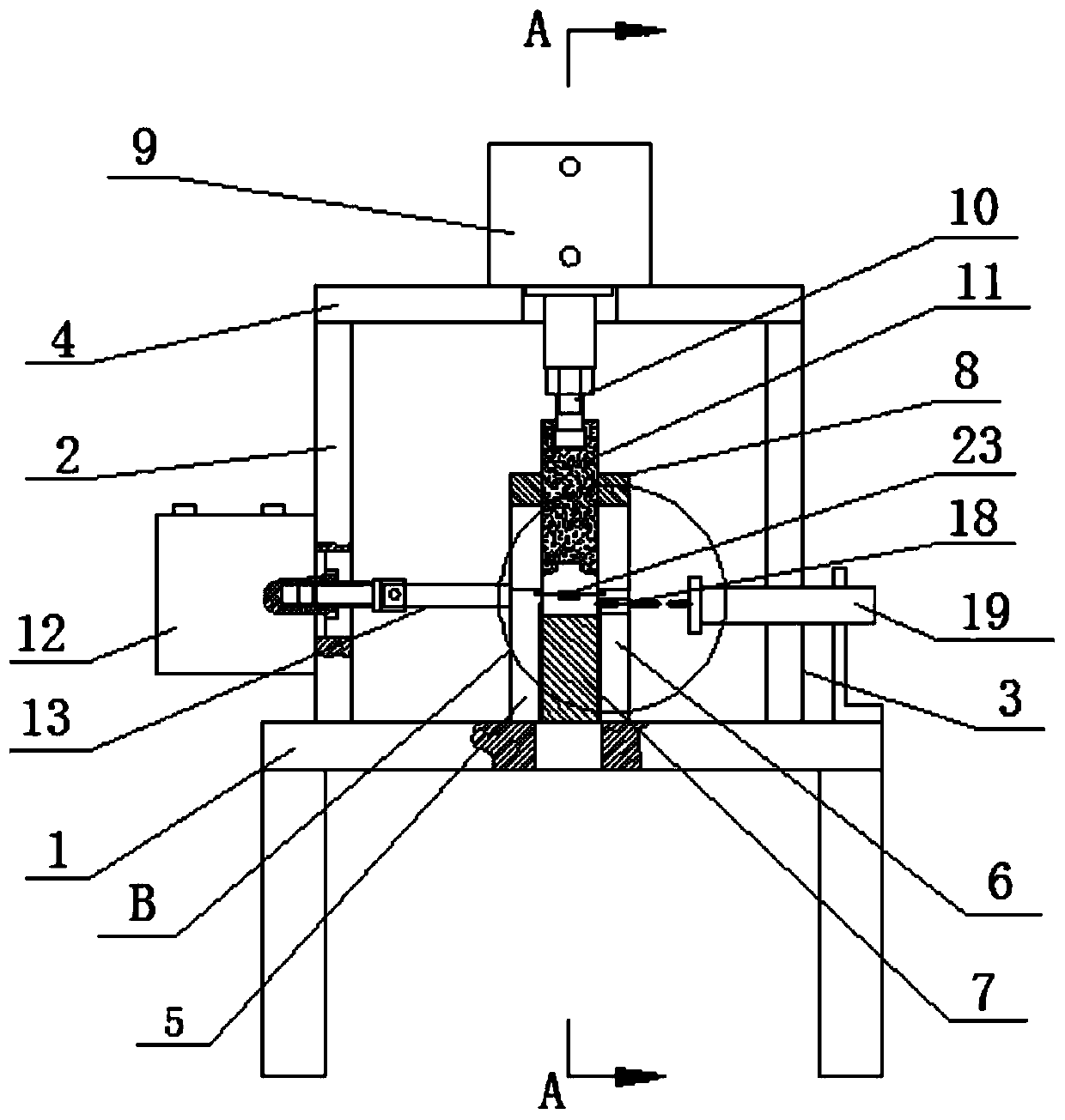
[0036] See Figure 3-Figure 6 , an automatic cutting device for an integrated circuit case lead frame, including a workbench 1, a punch support seat and a die fixed on the workbench 1, a punch drive cylinder 9 fixed on the punch support seat, and The punch drive cylinder 9 is connected to the punch 11 facing the die, and the exhaust cylinder 12 fixed on the punch support seat and facing the die, and the positioning push rod 13 connected to the exhaust cyl...


PUM


Abstract

The invention discloses automatic cutting equipment of an integrated circuit tube shell lead frame. The automatic cutting equipment comprises a workbench, a male die supporting seat, a female die, a male die driving air cylinder, a male die, an exhaust waste gas cylinder, a positioning push rod and a photoelectric control system, wherein the male die supporting seat and the female die are fixed onthe workbench, the male die driving air cylinder is fixed on the male die supporting seat, the male die is connected with the male die driving air cylinder and faces the female die, the exhaust wastegas cylinder which is fixed on the male die supporting seat and faces the female die, and the positioning push rod is connected to the exhaust waste gas cylinder. According to the automatic cutting equipment, the precise cutting of the integrated circuit tube shell lead frame is realized by adopting pneumatic technology, photoelectric sensing control technology and precise die blanking technology, and the automatic cutting equipment is automatically separated from a waste material, mechanically controlled, and accurately and rapidly cut.

Description

technical field [0001] The invention relates to the field of integrated circuit shell manufacturing, in particular to an automatic cutting device for the lead frame of the integrated circuit shell. Background technique [0002] See figure 1 The chip is packaged in the ceramic package 01 and connected to the external circuit through the lead 02. Due to the process requirements, the lead frame 03 integrated with the lead 02 cannot be removed before the chip packaging process is completed, and after the chip packaging process is completed, The lead frame 03 must be cut off; in order to ensure the requirements of the subsequent welding and wiring, the length error of the lead 02 must be within 0.5mm, there must be no burrs, and the lead cannot be bent and deformed. Since the outer surface is gold-plated, friction should be avoided as much as possible during the processing. [0003] At present, hand-held products are generally used, and the frame is cut off with a simple trimmin...

Claims


Application Information

Patent Timeline
Patent Type & Authority Applications(China)
IPC IPC(8): B21D28/14B21D45/02B21C51/00B30B15/26
CPCB21C51/00B21D28/14B21D45/02B30B15/26
Inventor 刘齐舟刘玉琦刘玉柱
Owner 刘玉琦
Why Eureka
Try Eureka