Tool-free fixed welding method for high-power IGBT module

A technology for fixing tooling and welding methods, which is applied to welding equipment, auxiliary devices, manufacturing tools, etc., can solve problems affecting the long-term service reliability of high-power IGBT modules, reduce production efficiency, and affect welding quality, etc., and achieve online automation The effect of production, simplification of welding process, and avoidance of solder overflow

Active Publication Date: 2019-08-20
NARI TECH CO LTD +1
View PDF8 Cites 6 Cited by
  • Summary
  • Abstract
  • Description
  • Claims
  • Application Information

AI Technical Summary

Problems solved by technology

[0004] For the solder paste process, there is no need for additional tooling during the soldering process, and the soldering efficiency is high. However, the solder paste contains a large amount of flux, which needs to be cleaned after soldering, and flux residues are likely to exist, which will seriously affect large-scale applications with high reliability requirements. Long-term service reliability of power IGBT modules
For the solder tab process, there is no need to use flux during the welding process, and the post-solder cleaning process is exempted, but the solder tab has no adhesion, and the relative position of the chip, solder tab, and liner subunits is likely to move during the assembly process, affecting the final welding quality. , it is necessary to design corresponding welding fixtures for each IGBT module, which reduces production efficiency and increases tooling management costs

Method used


Image

  • Tool-free fixed welding method for high-power IGBT module
  • Tool-free fixed welding method for high-power IGBT module

Examples


Embodiment Construction

[0025] The present invention will be further described below in conjunction with the accompanying drawings and specific embodiments.

[0026] Such as Figure 1 to Figure 2 As shown, this embodiment uses the EconoDUAL with a voltage of 1700V and a current of 600A TM Take the module of encapsulation type as an example, including the following steps:

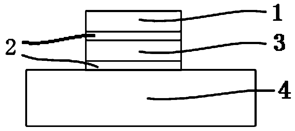
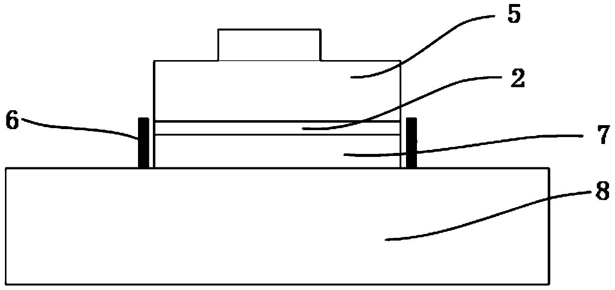
[0027] Step 1: Spray 2mg of polymer binder 2 on the back of the primary welding sheet 3, and then place the primary welding sheet 3 on the surface of the DBC liner 5 (copper-clad ceramic liner). The primary welding sheet 3 is a Sn90Sb10 alloy, and the polymer binder 2 is QPAC ® 40. The DBC liner 5 is an alumina ceramic copper-clad liner.

[0028] Step 2: Spray 2 mg of polymer binder 2 on the back of the chip 1, then place the chip 1 on the surface of the primary welding pad 3, assemble it into a lining subunit 5, and then put it into a welding furnace for primary welding. The chip 1 is a silicon-based chip, and the primary sold...


PUM

PropertyMeasurementUnit
thicknessaaaaaaaaaa
thicknessaaaaaaaaaa

Abstract

The invention discloses a tool-free fixed welding method for a high-power IGBT module. The method comprises the following steps that a polymer binder is sprayed on the back surface of a first weldinglug, and the first welding lug is placed on the surface of the copper-clad ceramic lining plate; the polymer binder is sprayed on the back surface of a chip, the chip is placed on the surface of the first welding lug, the chip and the first welding lug are assembled into a lining plate subunit, and the lining plate subunit is put into a welding furnace, thus finishing the first welding; an organicsilica gel is coated on the surface of the lining plate, the coating shape is a rectangular frame, and the size of the rectangular frame is larger than that of a secondary welding lug; the secondarywelding lug is placed in the rectangular frame of the organic silica gel; the polymer binder is sprayed on the back surface of the lining plate subunit, and the lining plate subunit is placed on the surface of the secondary welding lug, and then the lining plate subunit and the secondary welding lug are assembled together and put into the welding furnace, thus finishing the secondary welding. According to the method, a tool is not required for fixing, so that the welding reliability can be ensured; the cleaning is not needed; and the organic silica gel in the secondary welding can not only beused for fixing the welding lug, but also avoid the phenomena of overflow of welding flux on the surface of a base plate due to the fact that the large-size welding lug is melted, short circuit and the like.

Description

technical field [0001] The invention relates to the technical field of IGBT module welding, in particular to a method for fixing and welding high-power IGBT modules without frocks. Background technique [0002] Insulated Gate Bipolar Transistor (IGBT) is the most advanced power semiconductor device in the third generation of power electronic devices. It has the advantages of high frequency, high voltage and high current. The core devices in the fields of energy power generation and power quality management have been widely used in related industries. In IGBT module packaging, the welding of the chip and the Direct Bonding Copper (DBC) is usually called the primary welding; the welding of the lining subunit composed of the chip and the DBC lining and the copper or composite material substrate is called the second welding. First soldering, primary soldering and secondary soldering are key processes that affect the quality of module packaging. [0003] At present, the process...

Claims


Application Information

Patent Timeline
Patent Type & Authority Applications(China)
IPC IPC(8): B23K1/008B23K3/08
CPCB23K1/008B23K3/082
Inventor 杨金龙董长城骆健王立姚二现
Owner NARI TECH CO LTD
Why Eureka
Try Eureka