
Chip ferrite product electro-plating pre-treatment method

A technology for electroplating pretreatment and ferrite, which is applied in the field of electroplating pretreatment of chip ferrite products, and can solve the problems of uneven products, decreased welding performance of products with coating thickness, etc.

Active Publication Date: 2010-06-16
SHENZHEN SUNLORD ELECTRONICS
View PDF0 Cites 1 Cited by
  • Summary
  • Abstract
  • Description
  • Claims
  • Application Information

AI Technical Summary

Problems solved by technology

Second, the unevenness of the product in the electroplating process enables climbing plating to occur
The disadvantage of this method is that the reduction of the thickness of the coating will cause a decrease in the welding performance of the product

Method used


Image

  • Chip ferrite product electro-plating pre-treatment method
  • Chip ferrite product electro-plating pre-treatment method
  • Chip ferrite product electro-plating pre-treatment method

Examples


Embodiment 1

[0024] Embodiment 1: the electroplating pretreatment method of ferrite product, comprises the following steps:

[0025] 1. Dissolve the iron dispersant OA-01 (produced by Shanghai Maike Import and Export Co., Ltd.) in propyl acetate, and prepare four kinds of iron dispersant OA-01 with contents of 1‰, 2‰, 3‰, 5‰ of OA-01 solution.

[0026] 2. Place ferrite semi-finished products in glass cups containing four kinds of OA-01 solutions respectively. The volume ratio of ferrite semi-finished products and OA-01 solutions is 1:2.

[0027] 3. Put the four kinds of OA-01 solution glasses in the water of ultrasonic cleaning equipment with a water temperature of 55°C, the water level is 2 / 3 of the glass height, and the vibration time is 10 minutes.

[0028] 4. Take out the processed ferrite semi-finished product, wash it with 80°C pure water for 5 times, and complete the electroplating pretreatment process of the ferrite product.

[0029] Electroplate the above four ferrite semi-finis...

Embodiment 2

[0033] Embodiment 2: the electroplating pretreatment method of ferrite product, comprises the following steps:

[0034] 1. Dissolve iron dispersant OA-01 (manufactured by Shanghai Maike Import & Export Co., Ltd.) in propyl acetate to prepare OA-01 solution with a content of 3‰.

[0035] 2. Soak the ferrite semi-finished product in a glass cup filled with OA-01 solution for 10 hours. The volume ratio of ferrite semi-finished product to OA-01 solution is 1:2.

[0036] 3. Take out the processed ferrite semi-finished product, wash it with 80°C pure water for 5 times, and complete the electroplating pretreatment process of the ferrite product.

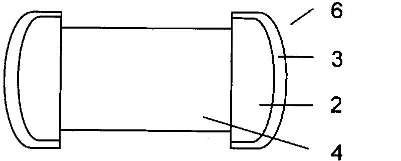
[0037] Electroplating the ferrite semi-finished product after the pre-plating treatment above: use barrel plating to electroplate a nickel layer and a tin layer on the outside of the silver terminal to obtain the following: image 3 The ferrite inductor finished product 6 shown in the figure, the magnet surface of the finished ferrite indu...


PUM


Abstract

The invention discloses a chip ferrite product electro-plating pre-treatment method, including the following processes: semi-finished product of chip ferrite after silver ink firing is placed into 0.1-3% solution composed of ferric dispersant and propyl acetate solvent for soaking for 10-24 hours and then is taken out when the surface of magnet is covered with a protective film; pure water at 55-100 DEG C is used for washing for 3-5 times, residual ferric dispersant on silver tip is cleaned, and then electro-plating can be carried out after product is placed into basket. The principle includes that the characteristic that ferric dispersant has strong affinity effect on ferric ion and weak affinity effect on silver is utilized to form a protective film on the surface of the magnet of semi-finished product of chip ferrite after silver ink firing. The invention has the beneficial technical effects that the chip ferrite product electro-plating pre-treatment process is convenient in operation, effect is good, and time is short. The invention not only can prevent climbing plating from being produced by semi-finished products of the chip ferrite after silver ink firing in electro-plating process, but also defect plating can not be caused, and welding reliability of electroplated chip ferrite product is ensured.

Description

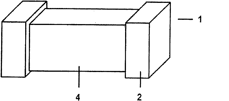
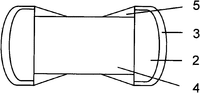
technical field [0001] The invention relates to a method for manufacturing chip ferrite products, in particular to a method for pre-plating electroplating of chip ferrite products. Background technique [0002] For chip ferrite products, there is a phenomenon that the electrodes at both ends extend toward the center in appearance, and the appearance defect of this kind of product is called climbing plating. The phenomenon of creep plating occurs in the electroplating process during the manufacturing process of the product. This electroplating process is the semi-product 1 after chip ferrite silver firing (see figure 1 ) on the terminal silver electrode 2 to deposit a layer of Ni metal layer and a layer of Sn metal layer respectively by electric current, that is, electroplating layer 3, so as to realize the weldability of the product. However, in actual operation, in addition to the terminal silver electrode 2, metal Ni and Sn will also be deposited inward along the termina...

Claims


Application Information

Patent Timeline
IPC IPC(8): C25D5/34
Inventor 郭海刘先忺戴春雷
Owner SHENZHEN SUNLORD ELECTRONICS
Learn More