
Method and device for filling sputtering film layer in groove

A sputtering film and filling method technology, applied in the field of display technology, can solve the problems of destroying the trench gate structure, device failure, TiN barrier layer failure, etc., and achieve the effect of ensuring the device structure, ensuring integrity, and avoiding nail penetration failure

Active Publication Date: 2019-08-20
BEIJING NAURA MICROELECTRONICS EQUIP CO LTD
View PDF6 Cites 0 Cited by
  • Summary
  • Abstract
  • Description
  • Claims
  • Application Information

AI Technical Summary

Problems solved by technology

[0003] In the prior art, when filling the IGBT trench, a high temperature above 500°C is used to increase the fluidity of Al, but too high a temperature will cause the failure of the TiN barrier layer and cause the interaction between Al and Si. Diffusion, pin-through
Al has passed through the barrier layer and entered the interior of Si, destroying the trench gate structure and making the device invalid; at the same time, part of Si is dissolved in Al, and when the temperature drops, Si in Al will be in a supersaturated state and precipitate out. Increasing the resistance will also degrade the performance of the device

Method used


Image

  • Method and device for filling sputtering film layer in groove
  • Method and device for filling sputtering film layer in groove
  • Method and device for filling sputtering film layer in groove

Examples


Embodiment Construction

[0045] In order to make the purpose, technical solutions and advantages of the embodiments of the present invention clearer, the technical solutions in the embodiments of the present invention will be clearly and completely described below in conjunction with the drawings in the embodiments of the present invention. Obviously, the described embodiments It is a part of embodiments of the present invention, but not all embodiments. Based on the embodiments of the present invention, all other embodiments obtained by persons of ordinary skill in the art without creative efforts fall within the protection scope of the present invention.

[0046] Terms used in the embodiments of the present invention are only for the purpose of describing specific embodiments, and are not intended to limit the present invention. The singular forms "a", "said" and "the" used in the embodiments of the present invention and the appended claims are also intended to include plural forms, unless the conte...


PUM

PropertyMeasurementUnit
thicknessaaaaaaaaaa
thicknessaaaaaaaaaa

Abstract

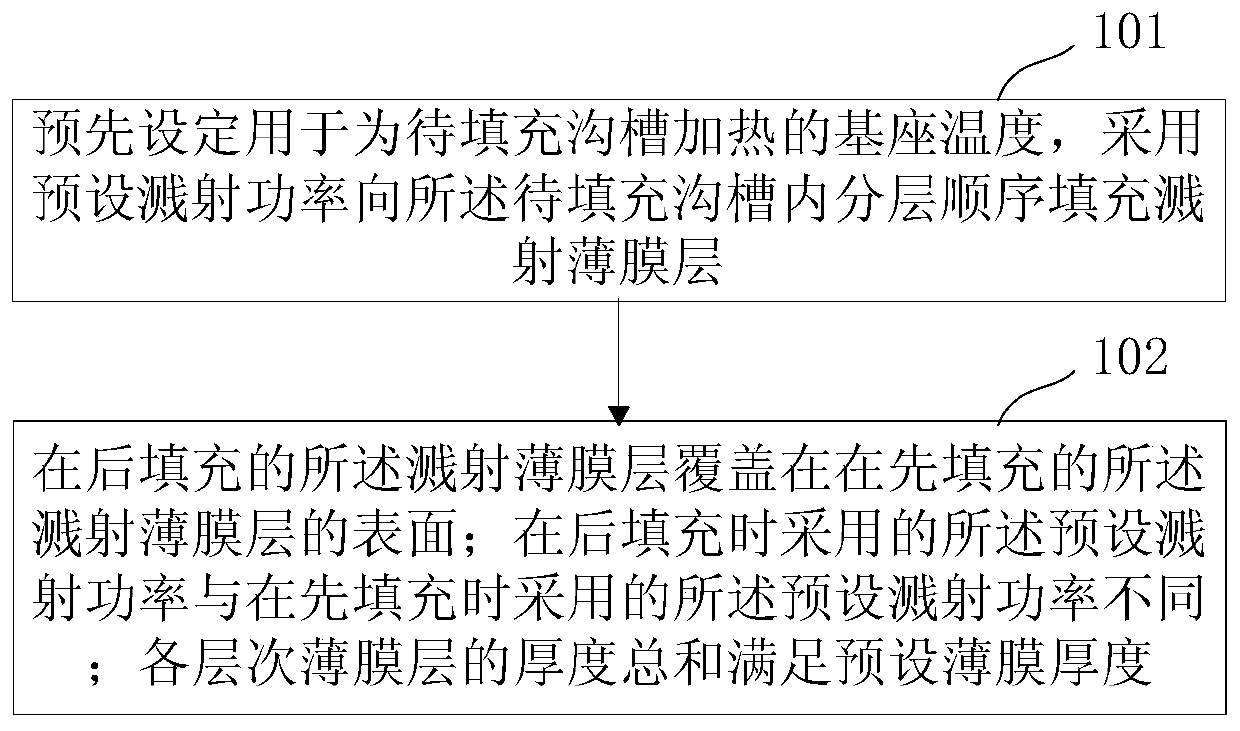
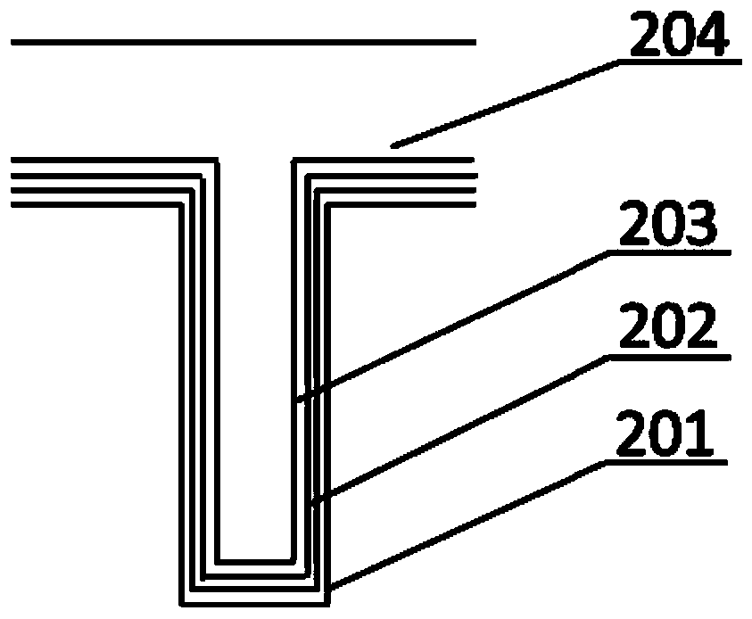
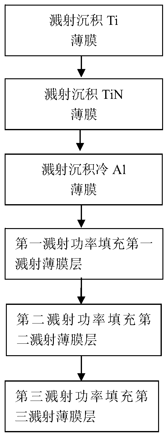
The embodiment of the invention provides a method and device for filling a sputtering film layer in a groove. The method includes the steps that the temperature of a base for heating a to-be-filled groove is pre-set, the sputtering film layer is filled into the to-be-filled groove in a layered and sequential mode by adopting the preset sputtering power, a later-filled sputtering film layer coversthe surface of the before-filled sputtering film layer, the adopted preset sputtering power during later filling is different from the adopted preset sputtering power during before filling, and the total of the thickness of the film layer at each layer meets the preset film thickness. When sputtering film layer filling is conducted on the groove with the high ratio of depth to width, filling can be conducted by dividing of multiple power levels under the preset temperature, during filling, a return and deposition alternate manner can be adopted, the groove inner hollow due to groove opening closing can be effectively prevented, the powers advances gradually in due order from bottom to top, the groove bottom nail failure can be effectively avoided, and the integrity of the device structureis ensured.

Description

technical field [0001] The invention relates to the technical field of display technology, in particular to a sputtering film layer filling method and device in a groove. Background technique [0002] Insulated Gate Bipolar Transistor (IGBT) devices have gradually replaced traditional power devices due to their high power, high frequency, and low loss, and have been used as key devices in emerging industries such as rail transit and high-voltage power transmission. widely used. Compared with planar gate IGBT, trench gate IGBT can significantly improve the trade-off relationship between on-state voltage drop and turn-off energy, and is more suitable for low-voltage and high-frequency applications. With the rapid development of IGBT trench gate technology, the gate voltage of the device forms an electron accumulation layer in the N drift region, which enhances the electron injection in the PIN (Positive Intrinsic Negative) diode, increases the carrier concentration on the sur...

Claims


Application Information

Patent Timeline
Patent Type & Authority Applications(China)
IPC IPC(8): C23C14/34C23C14/50C23C14/02C23C14/14H01L21/28H01L21/285H01L29/739
CPCC23C14/024C23C14/025C23C14/14C23C14/3492C23C14/50H01L21/28079H01L21/2855H01L29/7397
Inventor 宋海洋丁培军王厚工刘菲菲高晓丽
Owner BEIJING NAURA MICROELECTRONICS EQUIP CO LTD
Learn More