A method for biosensor resistance modulation encoding information
A biosensor and resistance adjustment technology, applied in the field of biosensors, can solve the problems of error, high material cost and high manufacturing cost
- Summary
- Abstract
- Description
- Claims
- Application Information
AI Technical Summary
Problems solved by technology
Method used
Image
Examples
Embodiment 1
[0042] Such as Figure 5 Shown is an unfabricated resistive element 400, which is a unit comprising electrical resistance in biosensing. An information code S1=(200,400] is set in advance, the operation command H=A, and the operation command R is to make H belong to the digital interval (200,400], and R reaches the effect of the equation through resistance adjustment, and the resistance adjustment includes the following steps:
[0043] The first step, preset information code S1=(200,400] in the measurement and analysis system;
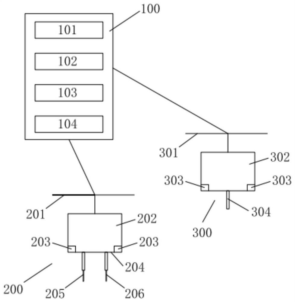
[0044] In the second step, the image acquisition device in the contact device collects the position of the probe and the position of the contact in real time, and transmits the position of the probe and the position of the contact to the recognition system and the image display system. The recognition system determines the position of the probe through image judgment. The display system displays images in real time;
[0045] In the third step, the re...
Embodiment 2
[0052] Set an information code S1=12 in advance, the operation command H is A2 / A1 and A3 / A1, the operation R is to make A2 / A1=A3 / A1=12, R achieves the effect of the equation through resistance adjustment, the resistance Conditioning consists of the following steps:
[0053] The first step is to preset the information code S1=12 in the measurement and analysis system;
[0054] In the second step, the image acquisition device in the contact device collects the position of the probe and the position of the contact in real time, and transmits the position of the probe and the position of the contact to the recognition system and the image display system. The recognition system determines the position of the probe through image judgment. The display system displays images in real time;
[0055] In the third step, the recognition system gives the command to the contact device "test the resistance value between the contacts a501 and b502". After the data receiver receives the comman...
Embodiment 3
[0064] Set an information code S1=123 in advance, the operation command H is A2+A1 and A3+A1 and A4-A1, the operation R is to make A2+A1=A3+A1=A4-A1, and R reaches the equation through resistance adjustment effect, the resistance adjustment includes the following steps:
[0065] The first step is to preset the information code S1=123 in the measurement and analysis system;
[0066] In the second step, the image acquisition device in the contact device collects the position of the probe and the position of the contact in real time, and transmits the position of the probe and the position of the contact to the recognition system and the image display system. The recognition system determines the position of the probe through image judgment. The display system displays images in real time;
[0067] In the third step, the recognition system gives the command to the contact device "test the resistance value between the contacts f806 and e805". After the data receiver receives the ...
PUM
 Abstract
Description
Claims
Application Information
 - R&D
- Intellectual Property
- Life Sciences
- Materials
- Tech Scout
- Unparalleled Data Quality
- Higher Quality Content
- 60% Fewer Hallucinations
Browse by: Latest US Patents, China's latest patents, Technical Efficacy Thesaurus, Application Domain, Technology Topic, Popular Technical Reports.
© 2025 PatSnap. All rights reserved.Legal|Privacy policy|Modern Slavery Act Transparency Statement|Sitemap|About US| Contact US: help@patsnap.com


