Vertical spinning machine for tank of cement tanker

A technology of cement tanker and spinning machine, applied in the field of spinning machine, can solve the problems of increasing the weight of the car body, reducing the load of the vehicle, complex process, etc., and achieve the effect of good overall quality, reduced manufacturing process, and good spinning effect

Inactive Publication Date: 2019-08-27
山东京华智能装备有限公司
View PDF0 Cites 2 Cited by
  • Summary
  • Abstract
  • Description
  • Claims
  • Application Information

AI Technical Summary

Problems solved by technology

[0003] The manufacture of traditional tank cars is relatively complicated. The tank body is welded by 4-5 sections of cone, cylinder, and head. The material is rolled and welded with equal thickness materials. reduce vehicle load

Method used


Image

  • Vertical spinning machine for tank of cement tanker
  • Vertical spinning machine for tank of cement tanker
  • Vertical spinning machine for tank of cement tanker

Examples


Embodiment 1

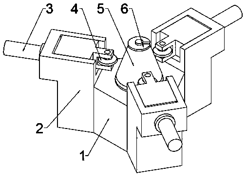
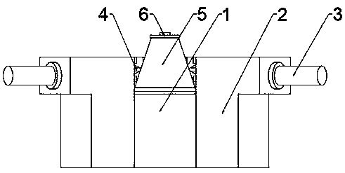
[0018] Example 1: Please refer to Figure 1-3 , a vertical spinning machine for a tank body of a cement tanker, comprising a frame 1, a spinning device 2 is evenly distributed on the side of the frame 1, and the spinning device 2 is connected to the side of the frame 1 by sliding up and down, and the spinning device 2 The upper part is slidably connected with a rotary wheel 4 through a hydraulic rod 3, and the moving direction of the hydraulic rod 3 is toward the middle of the frame 1; the inner side of the frame 1 is connected with a fixing mechanism through a rotating drive mechanism.

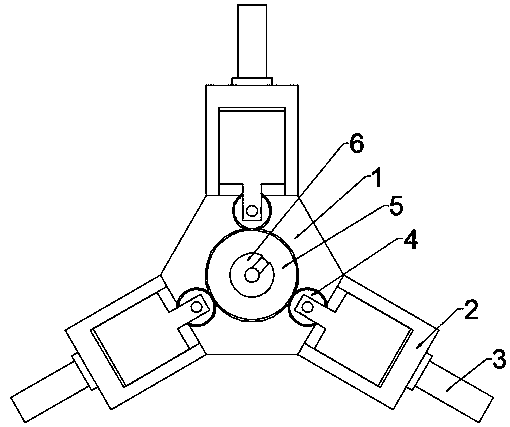
[0019] There are three spinning devices 2, which are distributed on the side of the frame 1 at 120°.

[0020] The fixing mechanism includes a mold 5 and a fixing plate 6 .

[0021] The fixed disk 6 is U-shaped.

Embodiment 2

[0022] Embodiment 2: This embodiment is a further improvement of the previous embodiment: the driving mechanism is a motor with high transmission efficiency.

[0023] The working principle of the present invention is: the device is a three-wheel hydraulic spinning machine, the central spindle rotates, the hydraulic cylinder in the center of the spindle presses the workpiece through the U-shaped disc, and the three rotary wheels 4 sequentially spin down the workpiece to make the workpiece thinner Stretching, while the blank is rotating with the main shaft of the bed, pressurize the blank with the rotary wheel 4 to make it produce local plastic deformation of the pressure tank head. Under the joint action of the feed motion of the rotary wheel 4 and the rotation motion of the blank, the local plastic deformation is gradually extended to the entire surface of the blank, and it is closely attached to the mold 5 to complete the spinning process of the part. The advantage of spinnin...


PUM


Abstract

The invention discloses a vertical spinning machine for a tank of a cement tanker, and relates to the spinning machine. The vertical spinning machine for the tank of the cement tanker comprises a rack, wherein spinning devices are uniformly distributed on the side surface of the rack and are up-and-down slidably connected to the side surface of the rack; spinning wheels are slidably connected above the spinning devices through hydraulic rods; the movement directions of the hydraulic rods face the middle of the rack; and a fixing mechanism is connected to the inner side of the rack through rotating a drive mechanism. More welding quality problems for traditional tank manufacturing exist, the flaw detection program is complex, and the overall weight problem is hard to solve. Through spinningmanufacturing, a non-welding process of a tank bottom component can be realized, the overall quality is good, light-weight manufacturing can be realized, the manufacturing cost is reduced, and an effective load is increased. Through spinning manufacturing, a mechanical performance of the tank is improved; and a grain structure of a material is changed through spinning, so that the mechanical strength is improved. The vertical spinning machine for the tank of the cement tanker provided by the invention adopts three vertical type rollers for multi-pass spinning so as to be applicable to spinning workpieces in different sizes; and the rollers are hydraulic driven so as to be sufficient in power and good in spinning effect.

Description

technical field [0001] The invention relates to a spinning machine, in particular to a vertical spinning machine for a cement tanker body. Background technique [0002] Spinning machine belongs to metal plastic forming machinery. An AC servo system is installed on the bed. The wheel frame in this system is provided with vertical and horizontal carriages perpendicular to each other. The horizontal and vertical feeding adopts precision ball screw pairs, which are driven by servo motors and synchronous belts. The pair is connected with the precision ball screw pair; there is a precision ball linear guideway under the carriage; a "copy" mechanism for the contour of the mandrel is provided on the top of the horizontal slide seat of the wheel frame; the CNC system device for controlling the servo system And the programmable logic controller that controls the hydraulic transmission system is connected with the industrial PC respectively. [0003] The manufacture of traditional ta...

Claims


Application Information

Patent Timeline
Patent Type & Authority Applications(China)
IPC IPC(8): B21D22/16B21D51/18
CPCB21D22/16B21D51/18
Inventor 赵晓辰
Owner 山东京华智能装备有限公司
Why Eureka
Try Eureka