Laser processing device and method for ceramic special-shaped groove

A technology of laser processing and laser devices, which is applied in the field of ceramic processing to achieve the effect of improving processing efficiency

Pending Publication Date: 2019-08-30
WUHAN HGLASER ENG CO LTD
View PDF3 Cites 5 Cited by
  • Summary
  • Abstract
  • Description
  • Claims
  • Application Information

AI Technical Summary

Problems solved by technology

[0004] The purpose of the present invention is to address the problems existing in the prior art, and to provide a device and method for laser processing ceramic irregular grooves, which can effect

Method used


Image

  • Laser processing device and method for ceramic special-shaped groove
  • Laser processing device and method for ceramic special-shaped groove
  • Laser processing device and method for ceramic special-shaped groove

Examples


no. 1 example

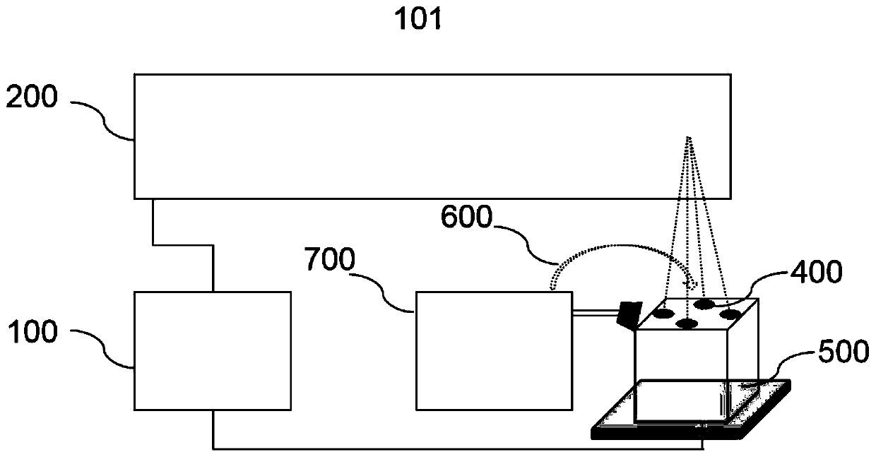
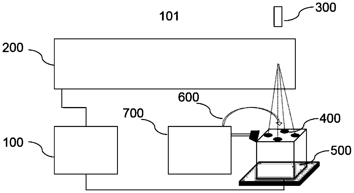
[0039] See figure 1 , figure 1 It shows a schematic view of the first view structure of the device for laser machining irregular-shaped ceramic grooves provided by the embodiment of the present application. The present application provides a device 101 for laser processing irregular-shaped ceramic grooves. The device 101 for laser processing irregular-shaped ceramic grooves includes: a control device 100, a laser device 200 and a motion device 500; the control device 100 is electrically connected to the laser device 200 and the motion device 500 respectively Sexually connected, the movement device 500 is arranged at the laser irradiation place emitted by the laser device 200 .

[0040] The control device 100 is used for simultaneously or separately sending control signals to the laser device 200 and the motion device 500 . The control signal includes a laser control signal sent to the laser device 200 and a motion control signal sent to the movement device 500 .

[0041] Th...

no. 2 example

[0059] See Figure 6 , Figure 6 A schematic flow chart of the method for laser machining irregular-shaped ceramic grooves provided by the embodiment of the present application is shown. The present application also provides a method of laser machining irregular-shaped ceramic grooves, the laser machining method comprising:

[0060] Step S11: According to the required taper value of the sample to be processed, calculate the distance of the rotating fixture from the center of the lens;

[0061] Step S12: the control device controls the rotary fixture to move to a designated position;

[0062] Step S13: The control device draws a processing layer of the sample to be processed according to the data of the sample to be processed, and the data includes the depth, taper size and rotation angle of the special-shaped groove of the sample to be processed.

[0063] Step S14: Calculate the number of layers according to the depth of the special-shaped groove of the sample to be process...

Embodiment approach

[0068] See Figure 7 , Figure 7 It shows a schematic flow chart of another implementation of the method for laser machining irregular-shaped ceramic grooves provided by the embodiment of the present application. Another embodiment of the method for laser machining irregular-shaped ceramic grooves provided by the present application is a processing method for laser-machining irregular-shaped ceramic grooves with a small taper. The steps of the processing method are as follows:

[0069] Step S21: According to the depth and taper of the required groove on the annular ceramic sample to be processed, the required processing layer is established through the control software in the computer.

[0070] Step S22: Calculate the required number of layers according to the required depth D of the groove to be processed and the processing depth d of each layer.

[0071] Step S23: Turn on the laser in the processing device, and set required parameters.

[0072] Step S24: Install the ring-...


PUM

PropertyMeasurementUnit
Wavelengthaaaaaaaaaa
Pulse widthaaaaaaaaaa

Abstract

The invention discloses a laser processing device for a ceramic special-shaped groove. The laser processing device comprises a control device, a laser device and a motion device, wherein the control device is electrically connected with the laser device and the motion device respectively; the motion device is arranged at a laser irradiation position emitted by the laser device; the motion device comprises rotary clamps and a three-dimensional platform; a support frame body is fixed on the three-dimensional platform; a plurality of rotary clamps are installed on the upper surface of the supportframe body; the bottom parts of the rotary clamps are connected with rotary motors; the top parts of the rotary clamps are fixedly connected with to-be-machined samples; the rotary motors are electrically connected with the control device, and to-be-machined samples clamped on the rotary clamps are controlled to rotate to a to-be-machined position; the three-dimensional platform is electrically connected with the control device, and to-be-machined samples clamped by the rotary clamps on the three-dimensional platform are controlled to move to a to-be-machined position. According to the laserprocessing device, the problem that taper of a special-shaped groove of a ceramic inner wall is too large after machining can be effectively solved under a common configuration; and machining efficiency is improved.

Description

technical field [0001] The invention relates to the technical field of ceramic processing, and relates to a device and a process method for processing ceramic inner walls by laser, in particular to a device and method for laser processing irregular-shaped ceramic grooves. Background technique [0002] Engineering ceramic materials have excellent physical properties and stable chemical properties, and have been widely used in industries such as machinery, electronics, aerospace and precision instruments, but their high brittleness and poor toughness have brought difficulties to fine processing, especially for Special-shaped grooves are processed by ceramics. Traditional machining accuracy is insufficient, and the chamfer between the side wall and the bottom of the groove is too large, resulting in poor subsequent assembly accuracy, and the ceramics after machining generally have quality problems such as residual stress and serious edge collapse. , so more and more industries ...

Claims


Application Information

Patent Timeline
IPC IPC(8): B23K26/36B23K26/064B23K26/402B23K26/70B23K26/142
CPCB23K26/064B23K26/0643B23K26/0648B23K26/142B23K26/36B23K26/402B23K26/702
Inventor 王建刚刘勇刘彪
Owner WUHAN HGLASER ENG CO LTD
Why Eureka
Try Eureka