Time phase quantum key distribution system transmitting end

A technology of quantum key distribution and time phase, which is applied in the field of the transmitter of the time phase quantum key distribution system, can solve the problems of large system bit errors, achieve good quality, simple system, and reduce system bit errors

Active Publication Date: 2019-08-30
ANHUI QASKY QUANTUM SCI & TECH CO LTD
View PDF3 Cites 8 Cited by
  • Summary
  • Abstract
  • Description
  • Claims
  • Application Information

AI Technical Summary

Problems solved by technology

[0006] To sum up, it is necessary to propose a new type of time-phase QKD system transmitter structure, and use this structure to solve the defect of large system error in the typical QKD system in the prior art

Method used


Image

  • Time phase quantum key distribution system transmitting end
  • Time phase quantum key distribution system transmitting end
  • Time phase quantum key distribution system transmitting end

Examples


Embodiment 1

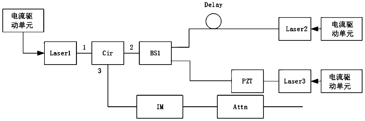
[0021] Embodiment 1: This embodiment provides a transmitter of a time-phase quantum key distribution system. This structure can be applied to transmitters of various QKD protocols including the BB84 protocol and the MDI protocol. Its typical structure is as figure 1 As shown, including semiconductor laser one (Laser1), circulator (Cir), optical beam splitter (BS1), optical delay line (Delay), piezoelectric ceramic ring (PZT), semiconductor laser two (Laser2), semiconductor laser three (Laser3), intensity modulator (IM), optical attenuator (Attn) and three current drive units.

[0022] The meaning and purpose of the above-mentioned components are respectively: the semiconductor laser (Laser) includes three semiconductor lasers, which are respectively semiconductor laser one (Laser1), semiconductor laser two (Laser2) and semiconductor laser three (Laser3): working in the gain switch mode , under current drive, narrow laser pulses can be generated. The function of the circulato...

Embodiment 2

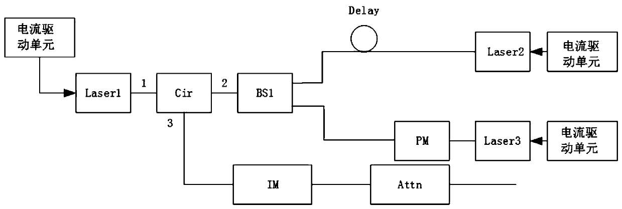
[0034] Example 2: see image 3 , this embodiment uses a phase modulator (PM) capable of rapidly modulating the phase to replace the PZT in Embodiment 1, and the rest of the structure is the same. The working principle of this embodiment is the same as that of Embodiment 1, and the effects are similar, and both are system structures protected by this patent.

Embodiment 3

[0035] Embodiment 3: see Figure 4 In this embodiment, an adjustable attenuator VOA is added after Laser1 to control the light intensity of Pulse1. Of course, the VOA can also be placed between port 2 of Cir and BS1, or placed in the upper and lower fiber arms behind BS1 (that is, there are adjustable attenuators on fiber arm 1 and fiber arm 2). The working principle of this embodiment is the same as that of Embodiment 1, and the effects are similar, and both are system structures protected by this patent.

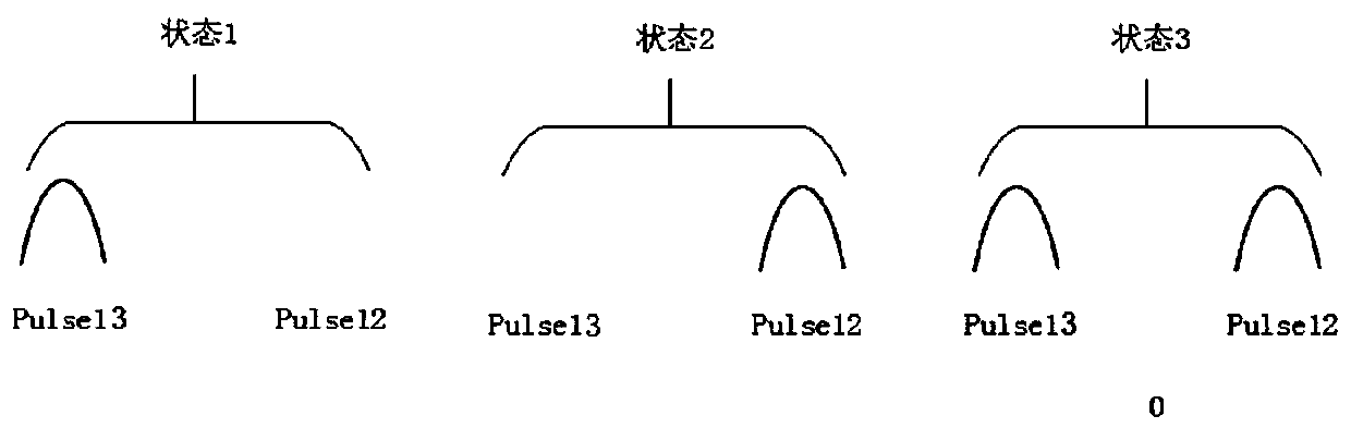
[0036] In summary, the present invention proposes a time-phase quantum key distribution system transmitter, this system structure can generate three kinds of quantum states for the time-phase QKD system, and compared with the typical system, because there are no Containing structures such as an external chopper, the system is simpler and cheaper. And because the quality of the generated optical pulse is better, the bit error of the system can be reduced. Typical applica...


PUM


Abstract

The invention discloses a time phase quantum key distribution system transmitting end. The transmitting end comprises a first semiconductor laser, a circulator, an optical beam splitter, an optical delay line, a phase modulation device, a second semiconductor laser, a third semiconductor laser, an intensity modulator, an optical attenuator and a current driving unit. The first semiconductor laseris connected with the circulator through an optical fiber, the circulator is connected with the optical beam splitter through an optical fiber, the optical beam splitter is connected with the second semiconductor laser through the first optical fiber arm, the first optical fiber arm is provided with an optical delay line, and the optical beam splitter is connected with the third semiconductor laser through the second optical fiber arm. The circulator is connected with the intensity modulator through an optical fiber, and the intensity modulator is connected with the optical attenuator throughan optical fiber; the phase modulation device is arranged on the first optical fiber arm or the second optical fiber arm; the first semiconductor laser, the second semiconductor laser and the third semiconductor laser are all connected with a current driving unit. The quality of the generated optical pulse is better, and the system error code can be reduced.

Description

technical field [0001] The invention belongs to the field of quantum key distribution technology (Quantum Key Distribution QKD), in particular to a transmitter of a time phase quantum key distribution system. Background technique [0002] Quantum cryptography communication combines the principles of quantum physics and modern communication technology. Quantum cryptography communication uses physical principles to ensure the security of the remote key negotiation process and results. Combined with the "one-time pad" encryption technology, it can realize secure communication that does not depend on the complexity of the algorithm. [0003] At present, quantum cryptography technology mainly uses photons as the realization carrier, which is distributed through free space or fiber optic channel. According to the requirements of different quantum key distribution protocols, quantum key distribution equipment uses various optical modulation devices to load classical random bits on...

Claims


Application Information

Patent Timeline
Patent Type & Authority Applications(China)
IPC IPC(8): H04B10/50H04B10/524H04B10/548H04B10/70H04L9/08
CPCH04B10/503H04B10/524H04B10/548H04B10/70H04L9/0819H04L9/0852
Inventor 丁禹阳王从柯程翌婷郝鹏磊
Owner ANHUI QASKY QUANTUM SCI & TECH CO LTD
Why Eureka
Try Eureka