Printing dying shaping machine waste gas recovery and treatment system

A waste gas recovery and treatment system technology, applied to chemical instruments and methods, dispersed particle separation, combined devices, etc., can solve the problems of high-voltage electrostatic device damage, cleaning, short life, etc., to prolong service life, improve work efficiency, The effect of improving the removal rate

Pending Publication Date: 2019-09-06
FUJIAN HANGGANG TEXTILE TECH CO LTD
View PDF1 Cites 0 Cited by
  • Summary
  • Abstract
  • Description
  • Claims
  • Application Information

AI Technical Summary

Problems solved by technology

However, in this spraying method, it is difficult to clean the exhaust gas due to its rising speed too fast. Finally, the exhaust gas entering the high-voltage electrostatic device also contains too much soot oil, which makes the high-voltage electrostatic device easily damaged and has a short life.

Method used


Image

  • Printing dying shaping machine waste gas recovery and treatment system
  • Printing dying shaping machine waste gas recovery and treatment system
  • Printing dying shaping machine waste gas recovery and treatment system

Examples


Embodiment 1

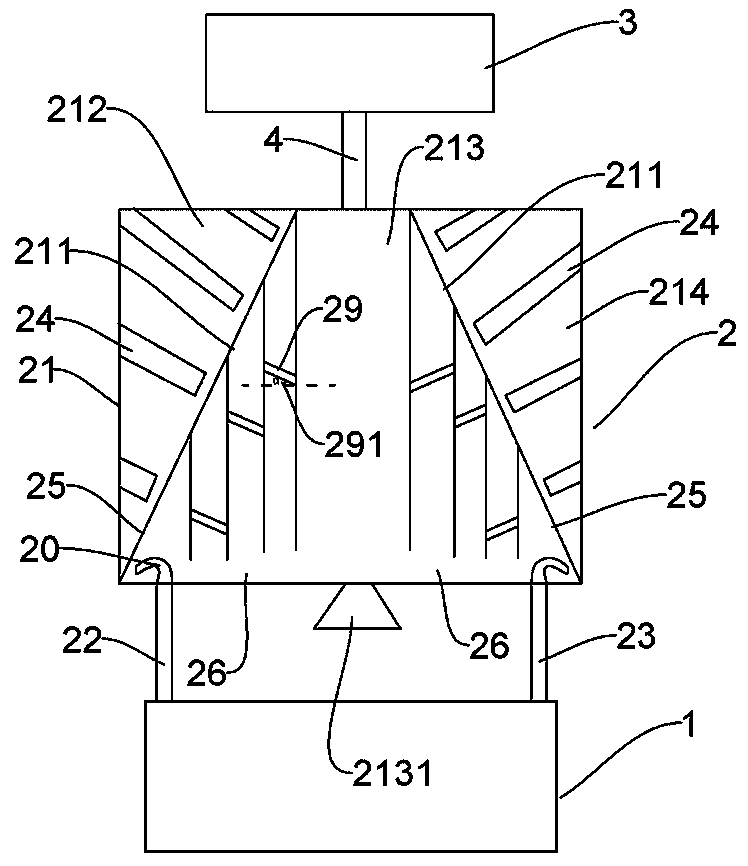
[0024] Such as figure 1 The exhaust gas recovery and treatment system of a printing and dyeing setting machine includes a waste heat recovery device 1 , a purification treatment device 2 and an electrostatic treatment device 3 .

[0025] One end of the waste heat recovery device 1 is connected to the waste gas outlet of the sizing machine, and the other end of the waste heat recovery device 1 is connected to the purification device 2, and the purification device 2 includes a housing 21 communicated with the waste heat recovery device 1 , the housing 21 is provided with two first partitions 211 to divide the housing 21 into a first nozzle area 212, a spray area 213 and a second nozzle area 214 in turn, and the bottom of the spray area 213 is two The upper end of the spray area 213 communicates with the electrostatic treatment device 3 through the third communication pipe 4. The first Both the nozzle area 212 and the second nozzle area 214 are provided with a plurality of nozzl...

Embodiment 2

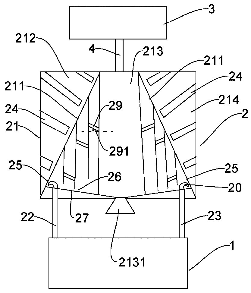
[0029] Such as figure 2 The exhaust gas recovery and treatment system of a printing and dyeing setting machine includes a waste heat recovery device 1 , a purification treatment device 2 and an electrostatic treatment device 3 . More preferably on the basis of embodiment 1:

[0030] The distance between the lower end of the second partition 25 and the bottom of the spraying area 213 decreases gradually from close to the corresponding first partition 211 to away from the corresponding first partition 211 , the first A partition 211 is provided with a drain plate 27 connected to the bottom of the spray area 213, the channel 26 is located between the drain plate 27 and the second partition 25, the first communication pipe 22 and the second The second communication pipe 23 communicates with a side of the flow guide plate 27 close to the corresponding first partition 211 . The setting of the diversion plate can let the water go out from the water outlet quickly, avoiding its acc...

Embodiment 3

[0033] Such as image 3 The exhaust gas recovery and treatment system of a printing and dyeing setting machine includes a waste heat recovery device 1 , a purification treatment device 2 and an electrostatic treatment device 3 . The difference from Example 2 is:

[0034] The water outlet 2131 communicates with the junction of the two diversion plates 27 .

[0035] The connecting pipe 29 is provided with a plurality of third through holes. The exhaust gas can also be sprayed to a certain extent through the third through hole, which can more effectively reduce the amount of soot in the exhaust gas.

[0036] And in this embodiment, the angle α is selected as 45°.


PUM


Abstract

The invention discloses a printing dying shaping machine waste gas recovery and treatment system, which comprises a waste heat recovery device, a purification treatment device and an electrostatic treatment device, wherein the purification device comprises a shell communicated to the waste heat recovery device, two first separation plates are arranged in the shell to sequentially divide the shellinto a first spraying nozzle area, a spraying area and a second spraying nozzle area, both ends of the bottom portion of the spraying area are respectively communicated to the waste heat recovery device through a first communication pipe and a second communication pipe, the upper end of the spraying area is communicated to the electrostatic treatment device through a third communication pipe, thetwo spraying nozzle areas are respectively provided with a plurality of spraying nozzles, the first separation plates are respectively provided with a plurality of first through holes, a plurality ofsecond separation plates are respectively arranged below the first separation plates, a channel for water flowing is arranged between the lower end of the second separation plate and the bottom portion of the spraying area, the second separation plates are respectively provided with a plurality of second through holes, and the bottom portion of the spraying area is provided with a water outlet. According to the present invention, the system has high waste gas heat energy recovery rate, the waste gas entering the electrostatic treatment device contains less soot oil, and the service life of thedevice is long.

Description

technical field [0001] The invention relates to the technical fields of energy saving, emission reduction and waste gas treatment in printing and dyeing, in particular to a waste gas recovery and treatment system of a printing and dyeing setting machine. Background technique [0002] With the continuous and rapid development of my country's industry, industrial production has also brought a certain degree of pollution to the environment, especially the problem of exhaust gas. If it is not purified and treated, it will be directly discharged into the atmosphere, which will seriously endanger people's health. [0003] The waste gas discharged from the sizing machine in the printing and dyeing industry is a high-temperature hot gas with a temperature of about 180°C. Exhaust gas contains various harmful components such as oil fume, dust and fabric fibers. If the exhaust gas is directly discharged into the atmosphere, it is neither environmentally friendly nor energy-saving. The...

Claims


Application Information

Patent Timeline
Patent Type & Authority Applications(China)
IPC IPC(8): B01D50/00
CPCB01D50/00
Inventor 郑春光林修禧裴元元张明陈文娟
Owner FUJIAN HANGGANG TEXTILE TECH CO LTD
Why Eureka
Try Eureka