Double-layer casing structure electric heating waste gas treatment device

An exhaust gas treatment device and a double-layer casing technology are applied in the direction of exhaust devices, noise reduction devices, machines/engines, etc., which can solve the problems of damage to electrical insulation ceramics of heating electrical components, potential safety hazards, unfavorable maintenance in the later period, etc., and achieve increased The effect of service life, reducing serious local aging problems, and avoiding core damage

Active Publication Date: 2021-07-27
亿达天地环保技术股份有限公司
View PDF16 Cites 0 Cited by
  • Summary
  • Abstract
  • Description
  • Claims
  • Application Information

AI Technical Summary

Problems solved by technology

[0005] Here, the known situation is: the prior art is usually an electric heating device with a single current circuit. In practical applications, this single current circuit is often limited by the diameter of the exhaust pipe or the vehicle-mounted power. During the design process, Based on the starting point of "the follow-up catalyst carrier should be heated as uniformly as possible", a circuit scheme of double current lines or multiple current lines appears. Obviously, this multi-path current scheme requires more electrical conductor joints and more The external circuit, which is unfavorable in assembly or later maintenance
[0006] As a rule, the electrical conductor is electrically conductively connected (welded or soldered) to an internally heated electrical component, where it has been proven that rotationally symmetrical structures surrounding the electrical conductor, usually with a ceramic insulating layer, may be used as electrical conductors Torques that, until now, could be greater than those generated by this insulation during conventional limited assembly, especially for subsequent maintenance or other types of repair work that require disassembly of electrical connections What's more, these situations will have a great possibility to cause damage to heating electrical components or electrically insulating ceramic bodies, thus bringing potential safety hazards

Method used


Image

  • Double-layer casing structure electric heating waste gas treatment device
  • Double-layer casing structure electric heating waste gas treatment device
  • Double-layer casing structure electric heating waste gas treatment device

Examples


Embodiment Construction

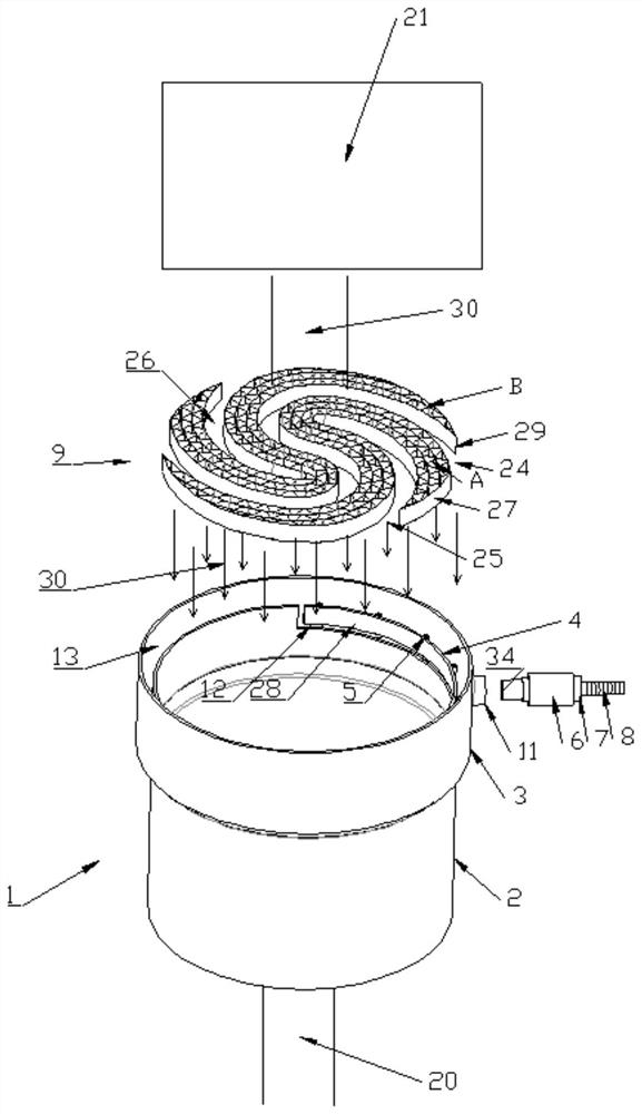
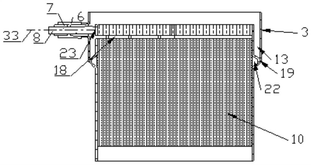
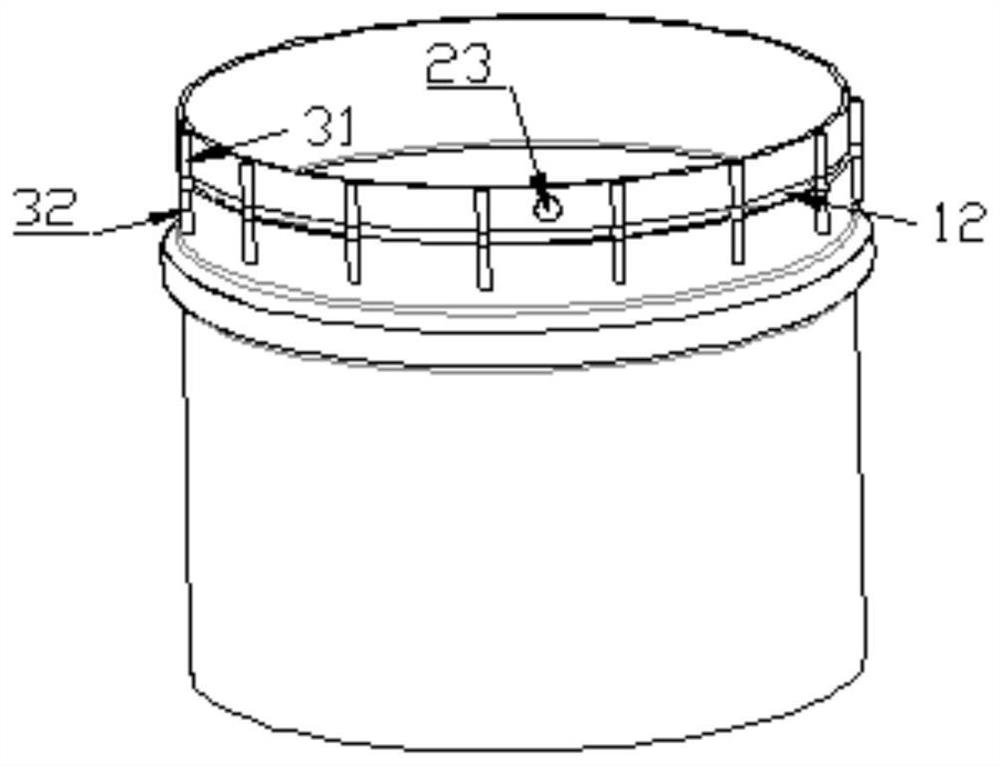
[0032] see figure 1 with 2 , shows the electric heating exhaust gas treatment device with double-layer casing structure of the present invention.

[0033] The electric heating exhaust gas treatment device 1 with a double-layer casing structure is used to purify the exhaust gas of the internal combustion engine 21, which is arranged in the exhaust system 20 of the internal combustion engine 21, and includes an inner casing 2, an outer casing 3 and a metal catalyst carrier 10. The metal catalyst carrier 10 is arranged inside the inner layer casing, and the upper outer edge of the inner layer casing 2 is provided with a trapezoidal reinforcing rib 19 protruding radially outward, and the outer diameter of the trapezoidal reinforcing rib 19 is equal to And the outer side is connected to the lower end inner wall of the outer casing 3, so that a double-layer casing gap 13 is formed between the outer casing 3 and the inner casing 2, and the double-layer casing gap 13 is preferably grea...


PUM


Abstract

An electric heating exhaust gas treatment device with a double-layer casing structure is arranged in the exhaust system of an internal combustion engine, and includes an inner layer casing, an outer layer casing and a metal catalyst carrier. The inner layer casing is provided with a metal catalyst carrier, and at least one The heating honeycomb element is located in the inner sleeve and arranged above the metal catalyst carrier. There is an insulating gap between the heating honeycomb element and the metal catalyst carrier. The upper end of the inner sleeve is located on the inner side of the outer sleeve and a The annular U-shaped processing groove separates the upper end of the inner casing into a circular arc, one end of the heating honeycomb element is electrically connected to the circular arc, and a conductive element is electrically connected to the circular arc after penetrating through the outer sleeve. The outer wall of the arc ring; thus, the present invention can effectively reduce or avoid the adverse effects of accelerated oxidation and corrosion in the contact area between the end of the electric conductor and the honeycomb core body, and especially avoid the high torque generated during the actual assembly process so that Damage caused by electrically sensitive parts.

Description

technical field [0001] The invention relates to the technical field of emission reduction of automobile tail gas pollutants, in particular to an electric heating waste gas treatment device with a double-layer casing structure. Background technique [0002] In the exhaust system of the internal combustion engine, an electric heating device that can play a catalytic role in advance is installed at the front end of the catalyst carrier. It can ignite the catalytic reaction through the flowing exhaust gas through radiant heat, especially for the rapid and effective heating of the diesel internal combustion engine. The accumulated carbon black particles are thereby burned off. [0003] The technical construction of this type of electric heating device is to use and only use a single sleeve, and to apply a circuitous current line at its end through equidistant gaps. One end of the current line is in contact with the inner wall of the sleeve, and the other end is in contact with an...

Claims


Application Information

Patent Timeline
Patent Type & Authority Patents(China)
IPC IPC(8): F01N3/20
CPCF01N3/2013
Inventor 夏哲
Owner 亿达天地环保技术股份有限公司
Why Eureka
Try Eureka