Machining method for coating layer of tool

A processing method and cutting tool technology, applied in the direction of metal material coating technology, coating, metal processing equipment, etc., can solve the problems of burning loss and hard phase particle feeding, so as to reduce the effect of burning loss and reduce the phenomenon of burning loss , Evenly distributed good effect

Active Publication Date: 2019-09-10
YANGJIANG KNIFESCISSOR HARDWARE RES INSTITUTION OF IND TECH +2
View PDF2 Cites 5 Cited by
  • Summary
  • Abstract
  • Description
  • Claims
  • Application Information

AI Technical Summary

Problems solved by technology

[0004] In order to overcome the deficiencies in the prior art, the object of the present invention is to provide a kind of processing method of tool coating, and this processing method has solved the feeding problem of hard phase particle that exists in the process of tool coating processing, burning problem and in The problem of uneven distribution in the coating improves the hardness, corrosion resistance and wear resistance of the tool coating, and ultimately improves the service life of the tool

Method used


Image

  • Machining method for coating layer of tool
  • Machining method for coating layer of tool
  • Machining method for coating layer of tool

Examples


Embodiment 1

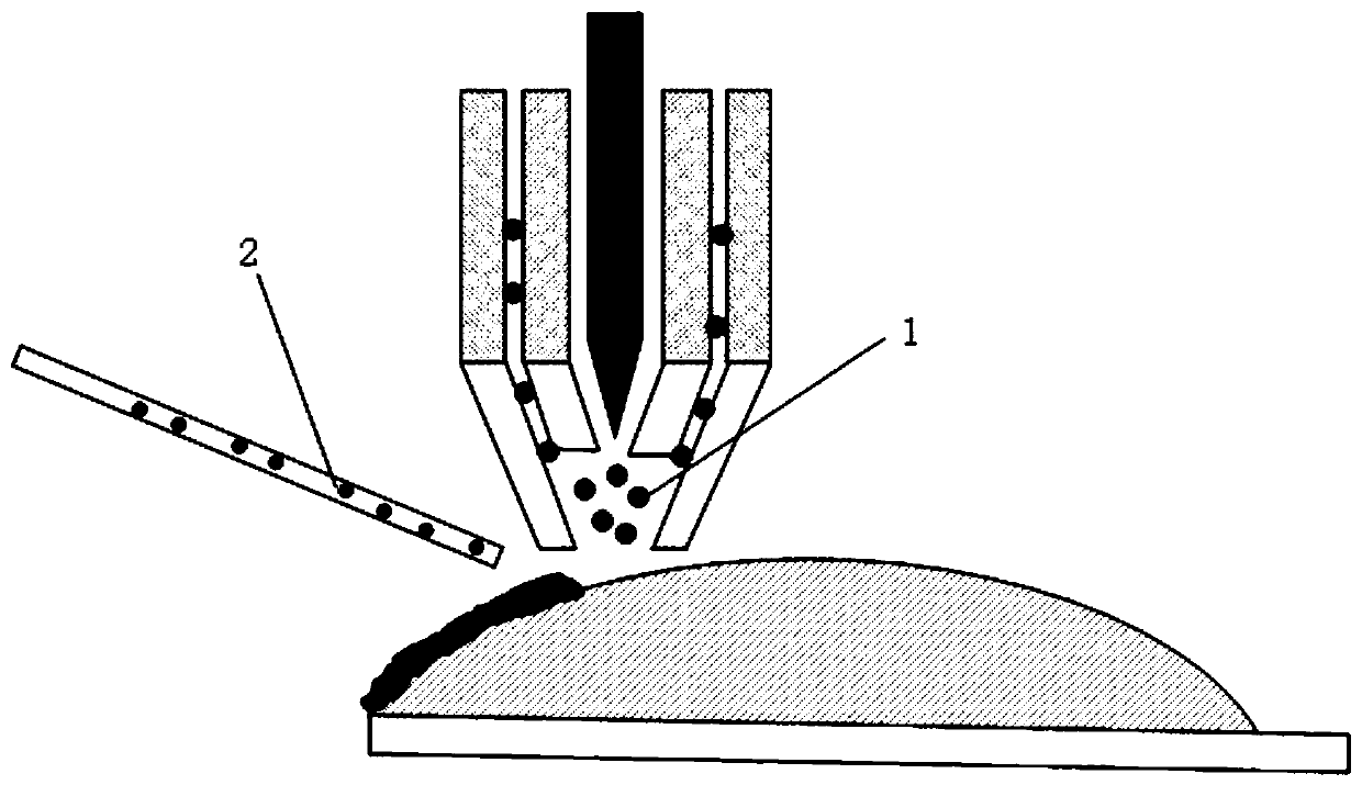
[0054] Such as figure 1 The schematic diagram of the process is shown, the binder phase 1 is fed from the coaxial powder feeding channel, and the reinforcing phase 2 is fed from the side shaft powder feeding channel.

[0055] A processing method for tool coating, comprising:

[0056] Melting pool formation step: the bonding phase is converged on the plasma arc heat source through the coaxial powder feeding channel, and the bonding phase is melted and deposited on the tool substrate (3Cr13) to form a molten pool; the bonding phase is stainless steel 3Cr13 (density 7.75g / cm 3 ), the particle size of the powder is 53-105 μm; the distance between the discharge nozzle of the coaxial powder feeding channel and the tool base material is 8mm, and the feeding speed of the binder phase is 10g / min;

[0057] Reinforcement phase addition step: send the reinforcement phase into the molten pool after the plasma beam is removed through the side axis powder feeding channel, and the density ...

Embodiment 2

[0065] A kind of processing method of tool coating

[0066] The mass ratio of binder phase and reinforcement phase is 3:2;

[0067] The particle size of the binder phase is 105-180 μm; the particle size of the reinforcing phase is 10-25 μm, and the Hall flow rate is 17 s / 50 g; other processing parameters are the same as in Example 1.

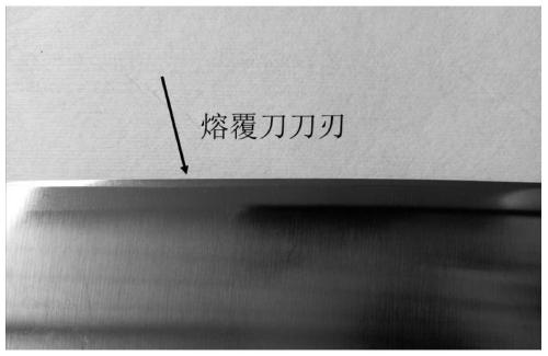
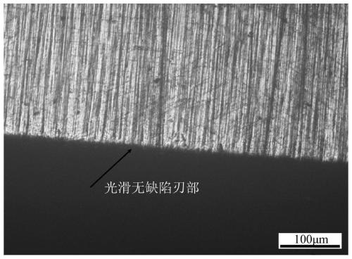
[0068] The surface morphology and metallographic pictures of the cutting tool are as follows: Figure 4-5 As shown, the surface morphology has no corrosion phenomenon and the phenomenon that the reinforcement phase particles fall off.

Embodiment 3

[0070] A kind of processing method of tool coating

[0071] The mass ratio of binder phase and reinforcement phase is 3:7;

[0072] The particle size of the binder phase is 120-200 μm; the particle size of the reinforcing phase is 15-25 μm, and the Hall flow rate is 16.5 s / 50 g; other processing parameters are the same as in Example 1.

[0073] The surface morphology and metallographic pictures of the cutting tool are as follows: Figure 6-7 As shown, the surface morphology has no corrosion phenomenon and the phenomenon that the reinforcement phase particles fall off.


PUM

PropertyMeasurementUnit
densityaaaaaaaaaa
particle diameteraaaaaaaaaa
angleaaaaaaaaaa

Abstract

The invention discloses a machining method for a coating layer of a tool. The machining method for the coating layer of the tool comprises a welding pool formation step and a reinforced phase adding step, wherein in the welding pool formation step, binding phases are converged at a plasma arc heat source through a coaxial powder feeding channel, and the binding phases are melted and then depositedon a base material of the tool to form a welding pool; and in the reinforced phase adding step, reinforced phases are conveyed into the welding pool after a plasma beam is removed through a side shaft powder feeding channel, and cladding is carried out on the binding phases and the reinforced phases under the condition of ultrasonic vibration to form the coating layer on the surface of the tool.According to the machining method, the problem of feeding for hard-phase particles, the problem of burning loss and the problem of non-uniform distribution in the coating layer, existing in a machining process for the coating layer of the tool, are solved, the hardness, the corrosion resistance and the wear resistance of the coating layer of the tool are improved, and finally the service life of the tool is prolonged.

Description

technical field [0001] The invention relates to a processing method for tool coating, which belongs to the technical field of material processing. Background technique [0002] At present, the commonly used preparation methods of surface composite coatings include electroplating, surface welding, vapor deposition, spraying, laser cladding, and plasma cladding. In order to increase the wear resistance and corrosion resistance of the coating, carbides or nitrides with high hardness, such as tungsten carbide, titanium carbide, vanadium carbide, etc., are often added in the process of preparing the coating. The base powder and the finer hard particle powder are evenly mixed through the ball milling process, and then the coating is prepared. However, complex solid-phase reactions will occur during the ball milling process of the base powder and hard phase particles, and the mechanical forces (shearing force, impact force, etc.) generated during the ball milling process can make ...

Claims


Application Information

Patent Timeline
Patent Type & Authority Applications(China)
IPC IPC(8): C23C24/10
CPCC23C24/103C23C30/00B23K10/027B23K2103/04C23C24/106C23C4/134C23C4/08
Inventor 张瑞华路超屈岳波肖梦智栗子林康平刘燕红邱桥华炳钟
Owner YANGJIANG KNIFESCISSOR HARDWARE RES INSTITUTION OF IND TECH
Why Eureka
Try Eureka