Dual motor regulated CVT electronic control system and method

An electronic control system and electronic control technology, applied in the direction of transmission control, mechanical equipment, components with teeth, etc., can solve the problems of interference, poor flexibility, high energy consumption, etc., and achieve simplified structure, convenient maintenance, and low energy consumption. Effect

Active Publication Date: 2019-09-10
JIANGSU UNIV OF TECH
View PDF6 Cites 0 Cited by
  • Summary
  • Abstract
  • Description
  • Claims
  • Application Information

AI Technical Summary

Problems solved by technology

[0005] Due to the interference of the rotation speed between the driving and driven wheels

Method used


Image

  • Dual motor regulated CVT electronic control system and method
  • Dual motor regulated CVT electronic control system and method
  • Dual motor regulated CVT electronic control system and method

Examples


Embodiment

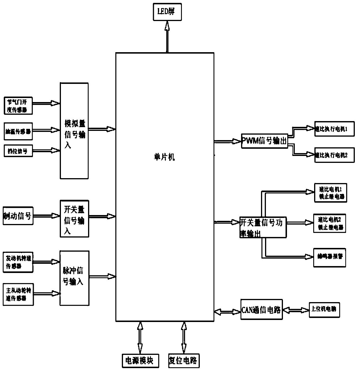
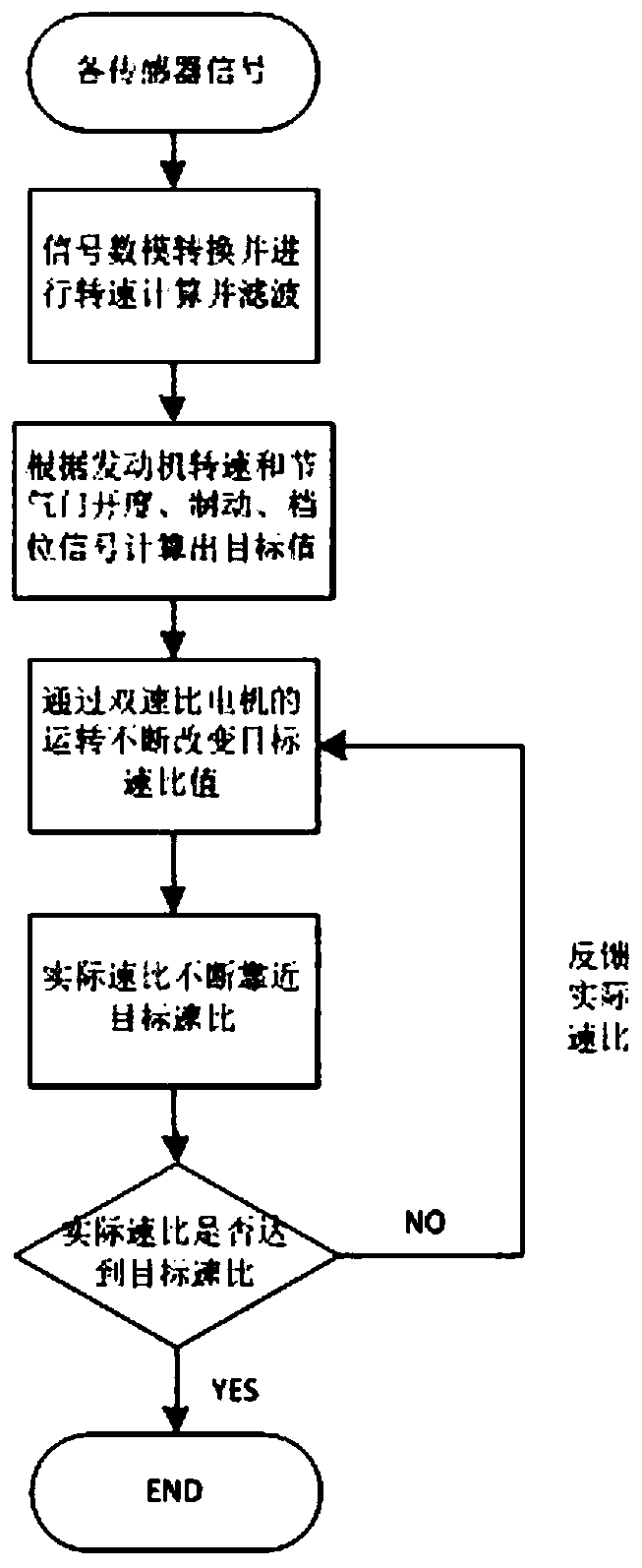
[0035] Such as figure 1 As shown, input the analog signal of the throttle opening and the gear position signal into the single chip microcomputer MC9S12G128. The single chip microcomputer has an AD conversion function, and the AD conversion can be realized after the system configuration; the braking signal is a switch signal, through the photoelectric coupling Filter out interference; the engine speed signal is shaped into a square wave signal by pulse signal through a voltage comparator. Since there is a certain functional relationship between the input variable value and the target speed ratio, the target speed ratio is obtained according to the input value of each sensor, and then the duty cycle of the output PWM signal value of the two PWM ports of the microcontroller is changed according to the target speed ratio value. Realize speed adjustment. During the adjustment process of the speed ratio motors, the two speed ratio motors work independently without interfering with...

Embodiment 2

[0044] The electronic control system includes a control circuit, a double-motor double-locking device, a power module, two speed-ratio execution modules, two speed-ratio motors, CAN network communication, an LED display, and a buzzer. The electronic control system mainly consists of a circuit board, a casing and a connector. The throttle opening signal and gear position signal input from the outside are input to the analog quantity of the single-chip microcomputer. The single-chip microcomputer has an AD conversion module inside, which converts the value of the analog quantity into a digital quantity, and then performs AD software filtering to obtain an effective value. At the same time, the vehicle brake signal is input. This signal is a switch value. In order to prevent interference, it needs to be input into the microcontroller through the switch signal circuit; the engine speed signal is input as a pulse signal, which is converted by the pulse measurement circuit, and the s...


PUM


Abstract

The invention discloses a dual motor regulated CVT electronic control system and method. The control system comprises a single chip microcomputer, externally-input throttle opening degree signals andgear position signals are input into an analog quantity of the single chip microcomputer, and the single chip microcomputer is internally provided with an AD conversion module; a vehicle brake signalis input to the single chip microcomputer, and the signal is a switch quantity; an engine rotating speed signal is input to be a pulse signal, conversion is carried out through a pulse measuring circuit, and the rotating speed calculated by a periodic method and a frequency method is input into the single chip microcomputer; a target speed ratio value is calculated in the single chip microcomputeraccording to the function relationship between the input signal and a target speed ratio, the target speed ratio value is used for changing the PWM duty ratio of two motor execution modules, the rotating speed of two speed ratio motors is continuously controlled in a coordinated manner, the actual speed ratio value continuously levels off to the target speed ratio value, and the final target speed ratio value is finally achieved; and the motors are locked through locking modules when the two speed ratio motors do not work, and the best performance of a vehicle is achieved.

Description

technical field [0001] The invention relates to a CVT gearbox in an automobile, in particular to electronic control in a double-motor CVT gearbox. Background technique [0002] The automobile industry took the lead in developing in Europe and North America. After more than 100 years of development, the automobile industry has matured. However, with the rapid development of automobiles, people have higher and higher standards for automobiles, mainly reflected in comfort and safety. , driving performance and economy. Cars bring great convenience to society, but with the increasing number of cars, energy crisis and environmental pollution follow. [0003] Therefore, technology is still in constant innovation, and cars will develop in the direction of reducing energy consumption and reducing pollution emissions in the future. A continuously variable transmission (Continuously Available Transmission, CVT) is a transmission that can continuously change the speed ratio. The CVT h...

Claims


Application Information

Patent Timeline
IPC IPC(8): F16H61/04F16H61/32F16H61/16F16H59/24F16H59/36F16H59/72F16H61/66
CPCF16H59/24F16H59/36F16H59/72F16H61/0437F16H61/16F16H61/32F16H61/66F16H2059/366F16H2061/0459F16H2061/326F16H2061/6602
Inventor 张兰春严芮孙阳张伟光张翰赵卓鹏周敏勇
Owner JIANGSU UNIV OF TECH
Why Eureka
Try Eureka