

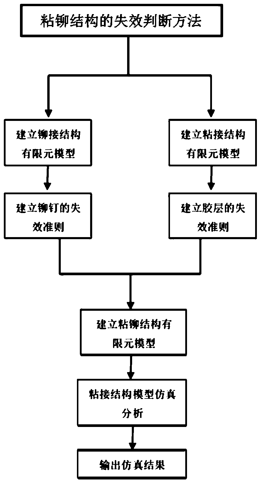
Failure judgment method for bonding-riveting connection structure
A technology of riveting and bonding, which is applied in the field of failure judgment of adhesive riveting structures, can solve the problems of easy aging of adhesives, electrochemical corrosion, high reliability, etc., to improve simulation accuracy, improve calculation efficiency, and ensure accuracy Effect
- Summary
- Abstract
- Description
- Claims
- Application Information
AI Technical Summary
Problems solved by technology
Method used
Image

Examples
Embodiment
[0071] In this embodiment, an arc-shaped beam with a riveted connection structure is used as the simulation object, and the method for judging the failure of the riveted connection structure provided by the present invention is further explained.
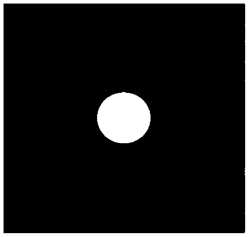
[0072] The carbon fiber arc-shaped rods are glued and riveted to the high-strength steel skeleton shell through aluminum alloy rivets and structural glue to form an arc-shaped beam. Since the curved beam is a symmetrical structure, half of the curved beam is selected for simulation calculation.
[0073] (1) Establish the finite element simulation model of the carbon fiber arc-shaped rod sticking riveting connection structure:
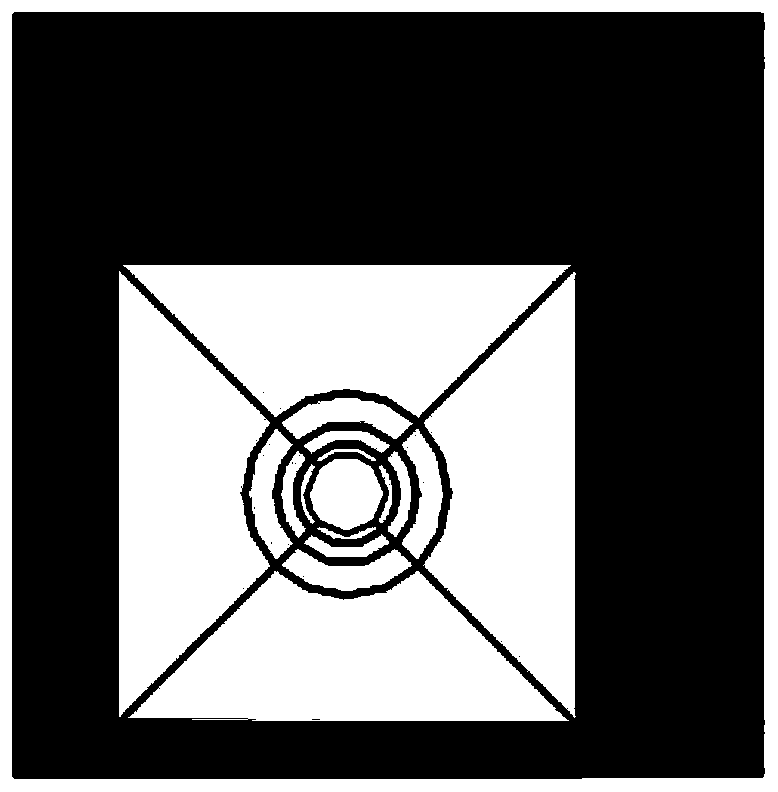
[0074] (a) Establishment of the geometric model of the carbon fiber arc-shaped rod joint adhesive riveted connection structure base material: utilize CATIA 20 version (the operating environment of all software of the present invention is the windows10 operating system) to establish the geometric model of the ...
PUM
 Abstract
Description
Claims
Application Information