Novel electromagnetic band gap structure for suppressing synchronous switch noise

An electromagnetic bandgap structure, synchronous switching noise technology, applied in the reduction of crosstalk/noise/electromagnetic interference (circuit devices, electrical components, etc.) question

Active Publication Date: 2019-09-10
HANGZHOU DIANZI UNIV
View PDF12 Cites 5 Cited by
  • Summary
  • Abstract
  • Description
  • Claims
  • Application Information

AI Technical Summary

Problems solved by technology

At present, the commonly used planar EBG structure is to etch the bandgap structure on the power plane to suppress the synchronous switching noise, but the current electromagnetic

Method used


Image

  • Novel electromagnetic band gap structure for suppressing synchronous switch noise
  • Novel electromagnetic band gap structure for suppressing synchronous switch noise
  • Novel electromagnetic band gap structure for suppressing synchronous switch noise

Examples


Embodiment Construction

[0029] The present invention will be further described in detail below in conjunction with specific embodiments of the accompanying drawings.

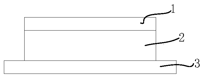
[0030] Such as figure 1 Shown is a schematic diagram of the structure of the present invention, from the top layer to the bottom layer are respectively a power plane 1, an insulating dielectric layer 2, and a complete ground plane 3, wherein the novel electromagnetic bandgap structure is etched on the power plane.

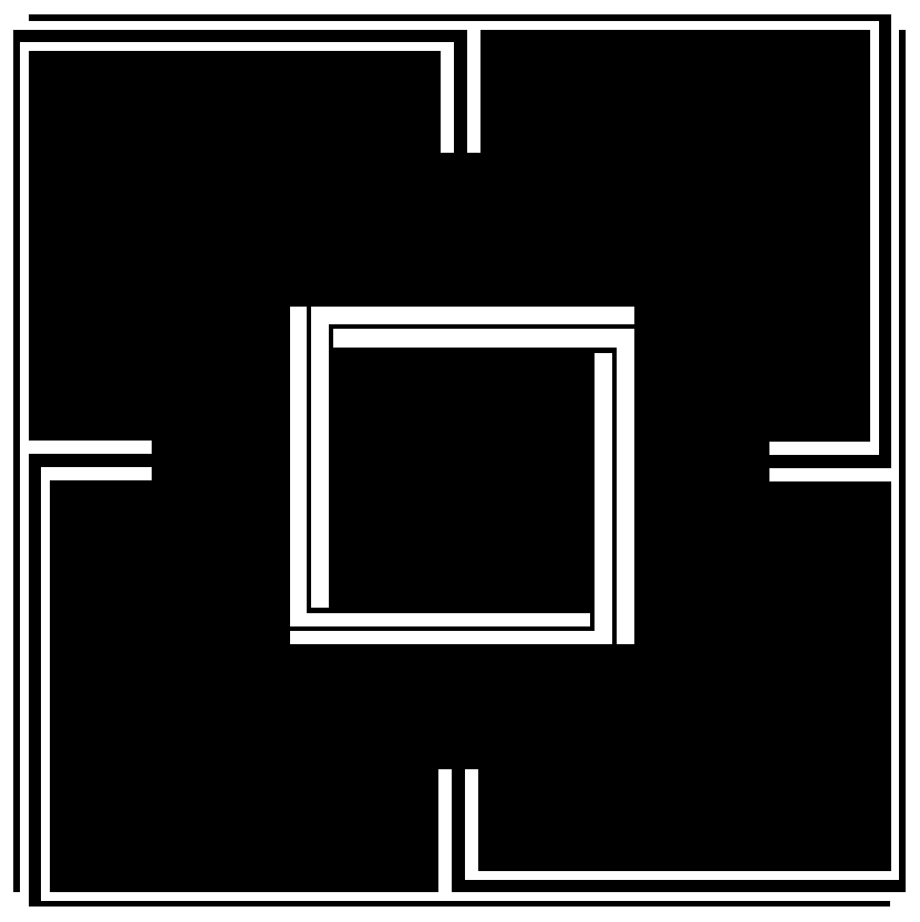
[0031] Such as figure 2 Shown is the structural basic unit schematic diagram of the present invention, and its basic unit structure is in a such as image 3 A vertical line groove is etched on each side of the power plane shown, and a microstrip line is drawn from the midpoint of the bottom of the groove, and the microstrip line surrounds the power plane in a counterclockwise direction to the end of its next side; The central area of ​​the power plane is a hollowed out area, embedded with a small square planar plate, and...


PUM

PropertyMeasurementUnit
Lengthaaaaaaaaaa
Media thicknessaaaaaaaaaa

Abstract

The invention discloses a novel electromagnetic band gap structure for suppressing synchronous switch noise. The electromagnetic band gap structure is etched on a power plane; all unit structures areconnected through S-shaped micro-strip lines; and an L-shaped micro-strip line is arranged in each unit structure. According to an S-shaped bridge structure, the inductance of a bridge structure of the electromagnetic band gap structure is increased, so that the lower cut-off frequency of noise suppression is reduced; and the S-shaped bridge structure can suppress the SSN in a stop band range to ensure that the noise cannot be transmitted to outside, so that the bandwidth range of the noise suppression is effectively expanded, and the ultra-wideband suppression of the SSN between the power plane and a ground plane is achieved. When the suppression depth is -40dB, the suppression bandwidth ranges from 0.26GHz to 25GHz.

Description

technical field [0001] The invention relates to a power distribution network with a miniaturized electromagnetic bandgap structure unit, in particular to a novel electromagnetic bandgap structure for suppressing synchronous switching noise. Background technique [0002] With the rapid development of microelectronics technology, modern electronic systems have higher and higher requirements for high performance, miniaturization, high integration and multifunctionality. However, the asynchronous switching of high-speed digital circuits can cause simultaneous switching noise (SSN), especially when the edge rate is uniform, the operating frequency is high, and the power supply voltage is low. The SSN between the power supply and the ground can cause severe signal and power integrity issues. Therefore, in mixed-signal systems, it is highly desirable to suppress SSN propagation within the wide stopband associated with good signals. In recent years, many researchers have tried var...

Claims


Application Information

Patent Timeline
IPC IPC(8): H05K1/02
CPCH05K1/0236H05K2201/093
Inventor 赵文生张园园王高峰
Owner HANGZHOU DIANZI UNIV
Why Eureka
Try Eureka