Novel charging system for electric vehicle

A technology for electric vehicles and charging systems, applied in electric vehicle charging technology, electric vehicles, charging stations, etc., can solve problems such as increased capital investment, low power factor, large switching loss, etc., to increase convergence speed and improve injection circuit waveforms Effect

Inactive Publication Date: 2019-09-13
HARBIN UNIV OF SCI & TECH
View PDF10 Cites 2 Cited by
  • Summary
  • Abstract
  • Description
  • Claims
  • Application Information

AI Technical Summary

Problems solved by technology

Since 2008, Japan has spent 200 million US dollars on research and development of electric vehicles every year. It is estimated that there will be more than 3,000 electric vehicles nationwide in 2030. Germany expects that 1 million electric vehicles will be put into transportation in 2020. The number of electric vehicles will double in 2030. By the middle of this century, the number of electric vehicles will occupy an absolute advantage and gradually replace traditional fuel vehicles. Therefore, my country has also increased investment in electric vehicles to keep up with the pace of the times. Electric vehicle charging The performance of facilities has become one of the elements for the smooth advancement of the electric vehicle industry. It not only determines the stability, charging times, and life span of electric vehicle batteries, but also directly affects the driving experience of users; however, the current DC chargers for electric vehicles in operation Most of them are composed of power electronic conversion circuits, etc., resulting in low harmonic generation and low power factor, large switching loss, and affecting the power quality of the power grid; It occupies an area and increases additional capital investment. In addition, there is still no simple and effective way to solve the problem that the output voltage is not adjustable.

Method used


Image

  • Novel charging system for electric vehicle
  • Novel charging system for electric vehicle
  • Novel charging system for electric vehicle

Examples


Embodiment Construction

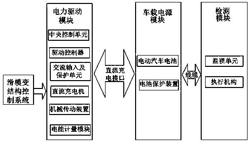
[0010] figure 1 It shows a new type of charging system for electric vehicles, which is mainly composed of an electric drive module, an on-board power supply module, and a detection module. The electric drive module includes a central control unit, a drive controller, an AC input and protection unit, a DC charger, a mechanical Transmission device, electric energy metering device; vehicle-mounted power supply module includes storage battery and battery protection device; detection module includes monitoring unit and actuator; the electric drive module and vehicle-mounted power supply module are connected to the charging and discharging monitoring system through optical fiber, and connected to PC through optical fiber communication The real-time monitoring of the battery is realized; the actuator is connected to the disconnector and the circuit breaker and then connected to the load, which is used to stop the power supply to the fully charged electric vehicle; the electric drive m...


PUM


Abstract

The invention discloses a novel charging system for an electric vehicle; a direct current charger of the system adopts an electric vehicle charger based on an improved rectifier, and a control systemof the improved rectifier adopts sliding mode variable structure control. The system is used for reducing harmonic current injected into a power grid by the electric vehicle charging system and improving the power quality of the power grid; in addition, the sliding mode variable structure control enables an output voltage and a load to have excellent dynamic adjustment characteristics when the output voltage and the load are greatly changed. Due to the superiority of the novel charging system structure of the electric vehicle, the utilization efficiency of electric power resources is improved.

Description

technical field [0001] The invention belongs to the field of power distribution systems, in particular to a new charging system for electric vehicles. Background technique [0002] Since the 21st century, with the development of global industry, the demand for energy has increased, and the impact on the ecological environment has also increased. Countries around the world have increasingly loudly called for improving environmental protection and reducing energy consumption. Countries have formulated a series of Laws and regulations require manufacturers to try to reduce emissions and develop non-polluting or ultra-low-pollution power sources. Energy-saving and environmentally friendly electric vehicles can slow down or replace traditional vehicles' dependence on oil. Taking this as a starting point, the world is promoting a revolution in automotive power technology Today, it is recognized that electric vehicles are the most promising solution to land transportation in the fu...

Claims


Application Information

Patent Timeline
Patent Type & Authority Applications(China)
IPC IPC(8): B60L53/62B60L58/10H02J3/01H02J3/18
CPCB60L53/62B60L58/10H02J3/01H02J3/18Y02T10/72Y02T10/70Y02T10/7072Y02T90/12Y02E40/30Y02E40/40
Inventor 颜景斌李瑞松李森铎
Owner HARBIN UNIV OF SCI & TECH
Why Eureka
Try Eureka