Dielectric gradient material and its application

A gradient material and dielectric technology, applied in magnetic materials, circuits, electrical components, etc., can solve the problems of limited application prospects, limited increase in dielectric constant, and limited influence of 3D insulator dielectric constant, etc., to achieve a wide range of applications and performance. Superior, wide gradient effect

Active Publication Date: 2019-09-13
SHENZHEN GRADUATE SCHOOL TSINGHUA UNIV
View PDF2 Cites 3 Cited by
  • Summary
  • Abstract
  • Description
  • Claims
  • Application Information

AI Technical Summary

Problems solved by technology

However, this technology achieves 2D dielectric distribution, which has limited influence on the dielectric constant of 3D insulators, and its application prospects are still limited.
[0005] The effectiveness of using dielectric gradient materials to homogenize the electric field and improve insulation performance has been verified by many research institutes. , the dielectric constant obtained by this method is limited, and it cannot provide the large gradient dielectric distribution required by the extremely inhomogeneous electric field

Method used


Image

  • Dielectric gradient material and its application
  • Dielectric gradient material and its application
  • Dielectric gradient material and its application

Examples


preparation example Construction

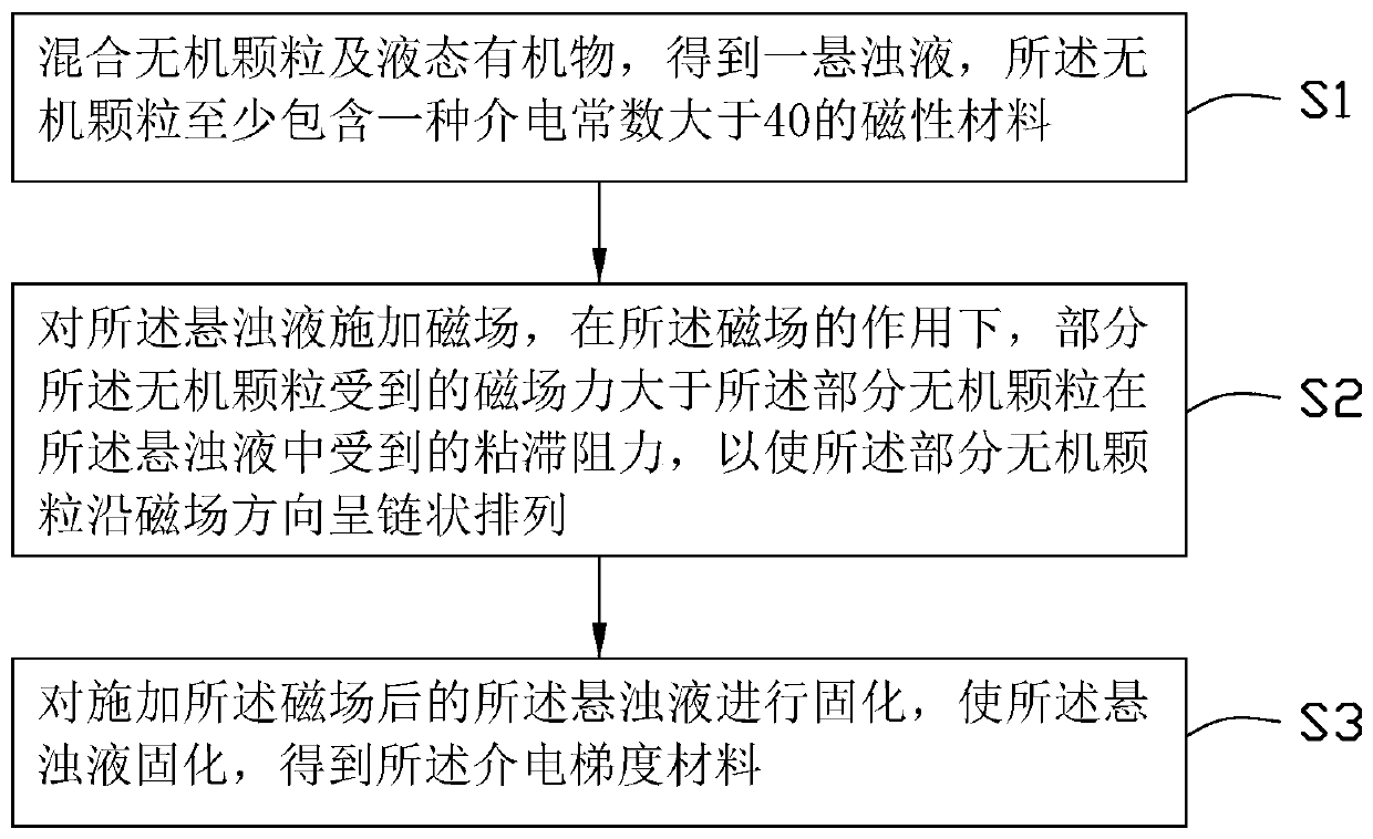
[0032] see figure 1 , a method for preparing a dielectric gradient material based on magnetic field induction provided by an embodiment of the present invention, comprising the following steps:

[0033] Step S1: mixing inorganic particles and liquid organic matter to obtain a suspension, the inorganic particles include at least one magnetic material with a dielectric constant greater than 40;

[0034] Step S2: applying a magnetic field to the suspension, under the action of the magnetic field, the magnetic field force on some of the inorganic particles is greater than the viscous resistance on the part of the inorganic particles in the suspension, so that The part of the inorganic particles is arranged in a chain along the direction of the magnetic field;

[0035] Step S3: performing solidification treatment on the suspension after applying the magnetic field to solidify the suspension to obtain the dielectric gradient material.

[0036] The inorganic particles are dispersed...

Embodiment

[0112] Add the photosensitive bisphenol A type epoxy acrylate resin and the defoamer TL-X60 into the mixing tank according to the ratio of 100:0.4 in parts by mass to obtain the mixed solution, stir at a speed of 600r / min for 0.5h in an ultrasonic environment, and Degas in a vacuum environment at 50°C for 0.5h.

[0113] Add the mixture, barium titanate@ferric oxide core-shell particles with a particle size of 1 μm and KH-560 silane coupling agent into the mixing tank according to the ratio of 100:2.5:0.0375 in parts by mass, and in an ultrasonic environment Stirring at a speed of 600 rpm for 0.5 hours, and degassing in a vacuum environment at 50°C for 0.5 hours to obtain a suspension, wherein, converted into a volume fraction, barium titanate@ferric oxide accounts for 1% of the total volume of the suspension 0.5%.

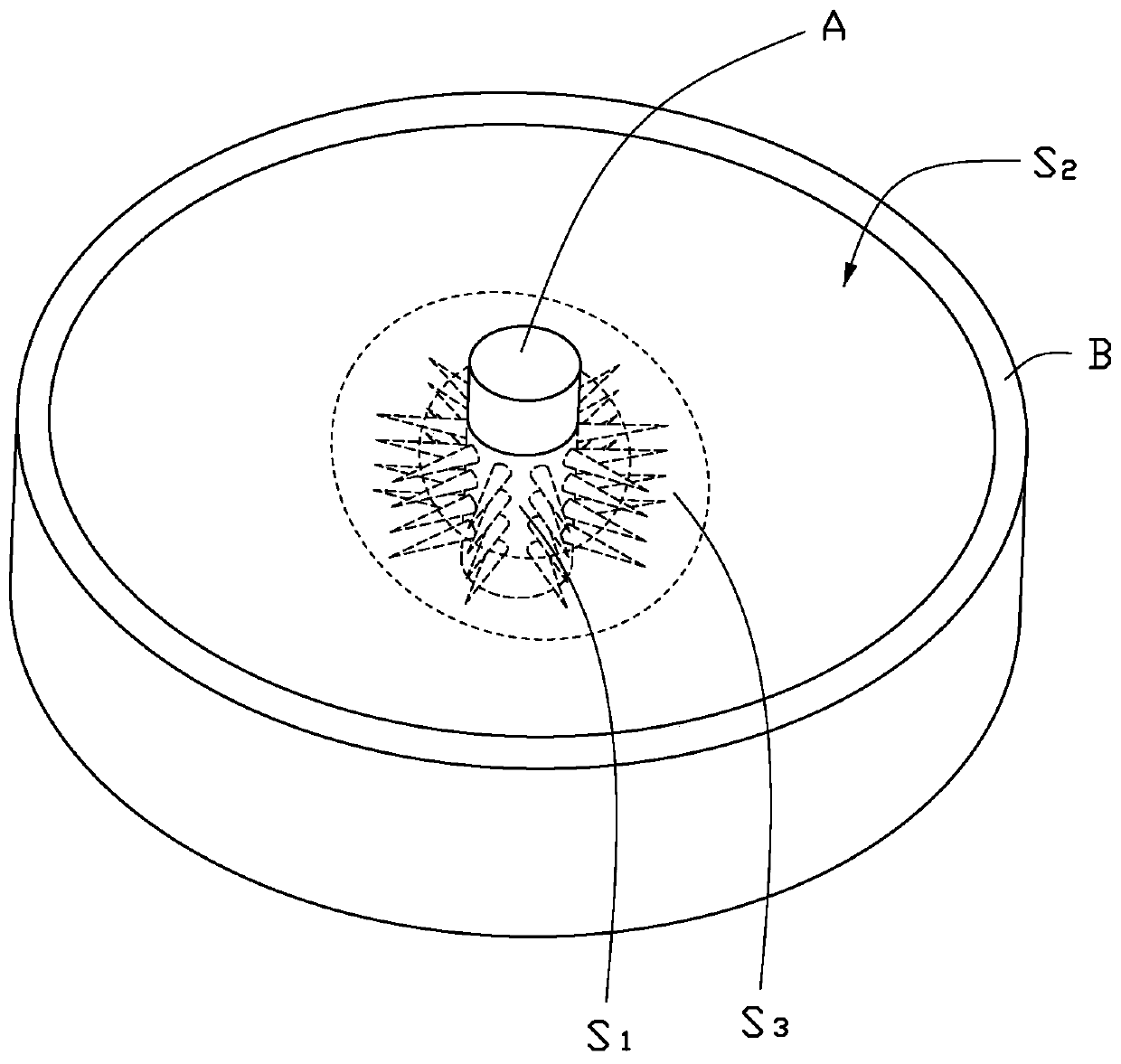
[0114] see Figure 4 , put the suspension in a disc-shaped mold, the disc-shaped mold is made of polytetrafluoroethylene material, the surface is coated with Jia...


PUM

PropertyMeasurementUnit
particle diameteraaaaaaaaaa
particle sizeaaaaaaaaaa

Abstract

The invention provides a dielectric gradient material, comprising a matrix material and filler particles, wherein the filler particles are dispersed in the matrix material, and the filler particles comprise at least one magnetic material having a dielectric constant greater than 40. The dielectric gradient material comprises a first region, a second region, and a third region located between the first region and the second region; the filler particles are arrayed in a chain in the first region and are disorderly distributed in the second region; the filler particles in the first region are inchain-shaped arrangement toward the second region; the filler particles are distributed in a disordered manner in the second region; and the filler particles distributed in the third region are in anordered-to-disordered transition state. The invention also provides the application of the dielectric gradient material. The filler particles in the dielectric gradient material provided by the invention are arranged in a chain in the first region, in a disordered manner in the second region and in the ordered-to-disordered transition state in the third region, so the dielectric gradient materialwith a gradient is constructed.

Description

technical field [0001] The invention relates to the technical field of insulating materials, in particular to a dielectric gradient material and its application. Background technique [0002] With the development of power systems towards EHV / UHV and large-capacity transmission, and the development of high-tech equipment such as pulse power, high-power microwave, and high-power semiconductor devices towards high voltage and miniaturization, the requirements for electrical insulation performance are becoming increasingly stringent , During the operation of the equipment, the problems caused by the failure of the insulation system, especially the solid insulation, are becoming more and more prominent. It is generally believed that the high non-uniformity of the electric field (local electric field distortion) is the root cause of insulation breakdown and flashover along the surface. At the interface of different media, such as the three junctions of electrodes, insulation and ...

Claims


Application Information

Patent Timeline
Patent Type & Authority Applications(China)
IPC IPC(8): C08L63/10C08K9/06C08K9/10C08K3/22C08K3/24C08J3/28H01F1/44
CPCC08J3/28H01F1/445C08J2363/10C08K9/06C08K9/10C08K2003/2275C08K3/24
Inventor 申子魁贾志东王希林张天枫
Owner SHENZHEN GRADUATE SCHOOL TSINGHUA UNIV
Why Eureka
Try Eureka