Dielectric gradient material and application thereof

A gradient material and dielectric technology, applied in the direction of circuits, electrical components, epoxy resin coatings, etc., can solve the problems of limited application prospects, limited dielectric constant improvement, unsatisfactory, etc., to achieve wide application range, superior performance, gradient wide range of effects

Active Publication Date: 2019-09-20
SHENZHEN GRADUATE SCHOOL TSINGHUA UNIV
View PDF5 Cites 8 Cited by
  • Summary
  • Abstract
  • Description
  • Claims
  • Application Information

AI Technical Summary

Problems solved by technology

However, this technology achieves 2D dielectric distribution, which has limited influence on the dielectric constant of 3D insulators, and its application prospects are still limited.
At present, the existing dielectric gradient materials have the disadvantages that it is difficult to meet the needs of insulation design, their flexibility and controllability are poor, the dielectric constant is limited, and they cannot meet the large gradient dielectric distribution required by the extremely uneven electric field.

Method used


Image

  • Dielectric gradient material and application thereof
  • Dielectric gradient material and application thereof
  • Dielectric gradient material and application thereof

Examples


preparation example Construction

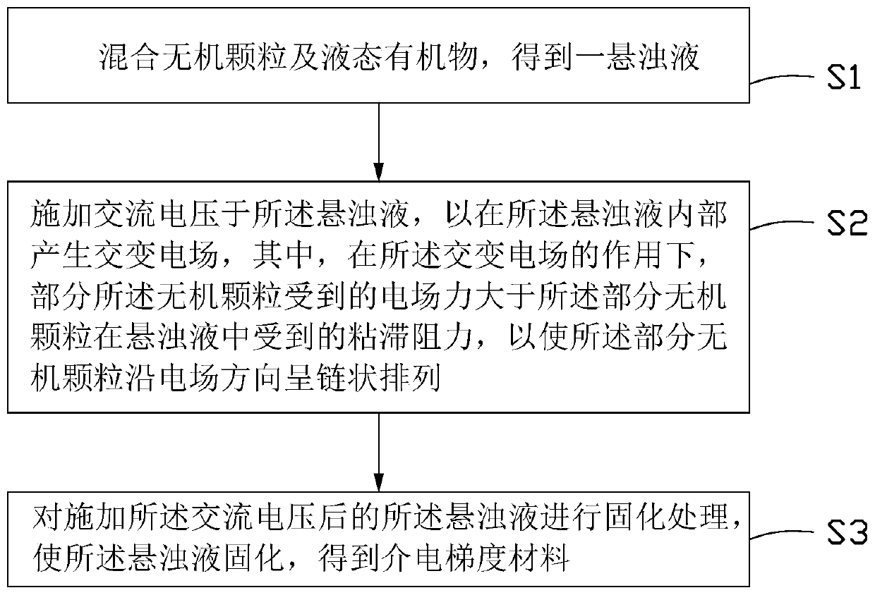
[0034] see figure 1, an embodiment of the present invention provides a method for preparing a dielectric gradient material induced by an electric field, comprising the following steps:

[0035] Step S1: mixing inorganic particles and liquid organic matter to obtain a suspension;

[0036] Step S2: applying an AC voltage to the suspension to generate an alternating electric field inside the suspension, wherein, under the action of the alternating electric field, some of the inorganic particles experience an electric field force greater than that of the Viscous resistance of part of the inorganic particles in the suspension, so that the part of the inorganic particles are arranged in a chain along the direction of the electric field;

[0037] Step S3: performing curing treatment on the suspension after applying the AC voltage to solidify the suspension to obtain the dielectric gradient material.

[0038] Inorganic particles are dispersed in the liquid organic matter, some of th...

Embodiment

[0113] Take epoxy resin E51 as a liquid organic matter, add it to a mixing tank, then add methyl hexahydrophthalic anhydride (MeHHPA) as a curing agent, dimethylbenzylamine (BDMA) as an accelerator, and epoxy resin to the mixing tank. TL-X60 is as defoamer, wherein the mass ratio of epoxy resin E51, curing agent, promotor and defoamer is 100:86:1:0.8, stirs 0.5 hour with the speed of 600 rev / mins; Then to Add 20 parts of barium titanate particles with a particle size of 1 μm as inorganic particles in the mixing tank, wherein the volume fraction of barium titanate particles is 2%, and add 0.075 parts of silane as a coupling agent, and in an ultrasonic environment at 600 Stir at a speed of rpm for 0.5 hour, and degas in a vacuum environment at 50° C. for 0.5 hour to obtain a homogeneous suspension.

[0114] The suspension was poured into a mold, the mold was made of polytetrafluoroethylene material, the surface of the mold was coated with Jiadan as a release agent, the center wa...


PUM

PropertyMeasurementUnit
particle diameteraaaaaaaaaa

Abstract

The invention discloses a dielectric gradient material. The dielectric gradient material comprises a matrix material and filler particles, wherein the filler particles are dispersed in the matrix material; the dielectric constant of at least one filler particle is greater than 40; the dielectric gradient material comprises a first region, a second region and a third region located between the first region and the second region; the filler particles are arranged in a chain shape towards the second region in the first region; the filler particles are in unordered distribution in the second region; and the filler particles are in ordered to unordered transition distribution in the third region. The invention also provides an application of the dielectric gradient material. The filler particles in the dielectric gradient material provided by the invention are arranged in the chain shape in the first region, are in unordered distribution in the second region and are in ordered to unordered transition distribution in the third region, so that the dielectric gradient material with the dielectric constant with the gradient is constructed; and the dielectric gradient material has the characteristics of being large in gradient range, wide in application range, excellent in performance and the like.

Description

technical field [0001] The invention relates to the technical field of insulating material preparation, in particular to a dielectric gradient material and its application. Background technique [0002] With the development of power systems towards EHV / UHV and large-capacity transmission, and the development of high-tech equipment such as pulse power, high-power microwave, and high-power semiconductor devices towards high voltage and miniaturization, the requirements for electrical insulation performance are becoming increasingly stringent , During the operation of the equipment, the problems caused by the failure of the insulation system, especially the solid insulation, are becoming more and more prominent. It is generally believed that the high non-uniformity of the electric field (local electric field distortion) is the root cause of insulation breakdown and flashover along the surface. At the interface of different media, such as the three junctions of electrodes, insu...

Claims


Application Information

Patent Timeline
Patent Type & Authority Applications(China)
IPC IPC(8): H01B3/02H01B3/10H01B3/12H01B3/28H01B3/30H01B3/36H01B3/40H01B3/44H01B17/14H01B17/38H01B17/58H01B17/60C09D163/00C09D5/25C09D7/61
CPCC09D5/00C09D163/00C09D7/61H01B3/02H01B3/025H01B3/10H01B3/12H01B3/28H01B3/30H01B3/36H01B3/40H01B3/44H01B17/14H01B17/38H01B17/583H01B17/60C08K3/24
Inventor 申子魁贾志东王希林张天枫
Owner SHENZHEN GRADUATE SCHOOL TSINGHUA UNIV
Why Eureka
Try Eureka