Eureka AIR delivers breakthrough ideas for toughest innovation challenges, trusted by R&D personnel around the world.

Method for forming overlying crust on surface of dredging silt slurry storage yard and overlying crust

A technology of silt slurry and hard shell layer, which is applied in the field of foundation treatment, which can solve the problems of low degree of mechanization, large consumption of curing agent, and slow construction speed, and achieve the effects of improving construction efficiency, shortening construction period, and reducing moisture content

Pending Publication Date: 2019-09-17
HUAZHONG UNIV OF SCI & TECH
View PDF0 Cites 5 Cited by
  • Summary
  • Abstract
  • Description
  • Claims
  • Application Information

AI Technical Summary

Problems solved by technology

[0008] On the one hand, all involve human labor in an extremely unfavorable environment, with a low degree of mechanization and extremely slow construction speed, seriously lagging behind the construction period;
[0009] On the other hand, for newly dredged silt slurry (water content usually >300%), the curing efficiency of the cement curing method is negligible. In order to achieve the predetermined solidified silt strength, a large amount of curing agent is required, which increases the project cost to a certain extent.

Method used


Image

  • Method for forming overlying crust on surface of dredging silt slurry storage yard and overlying crust
  • Method for forming overlying crust on surface of dredging silt slurry storage yard and overlying crust
  • Method for forming overlying crust on surface of dredging silt slurry storage yard and overlying crust

Examples


Embodiment 1

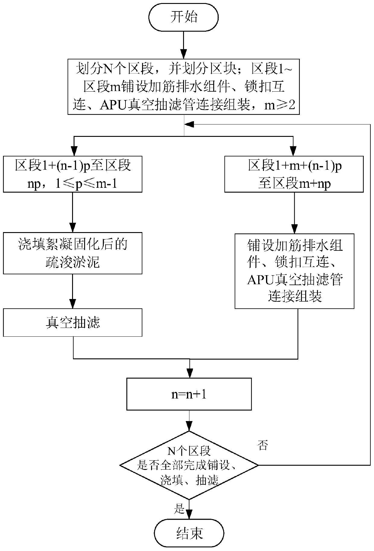
[0047] [Example 1] m=2, p=1

[0048] (1) Use a pumping device to pump the dredged sludge with a moisture content of up to 500% to the combined flocculation and solidification treatment unit for uniform stirring at a stirring speed between 60r / min and 120r / min until the flocculation and solidification process is completed; The work can be done ahead of time or during the sectioning and laying process.

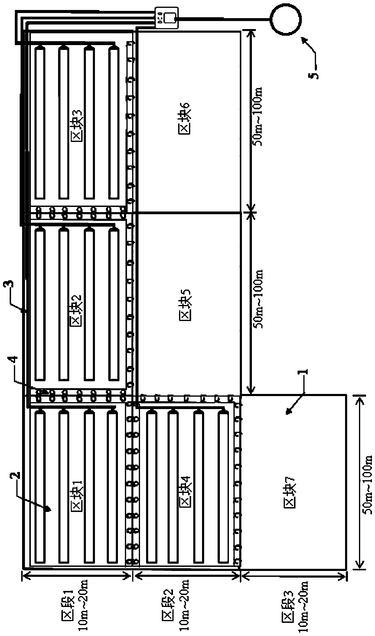
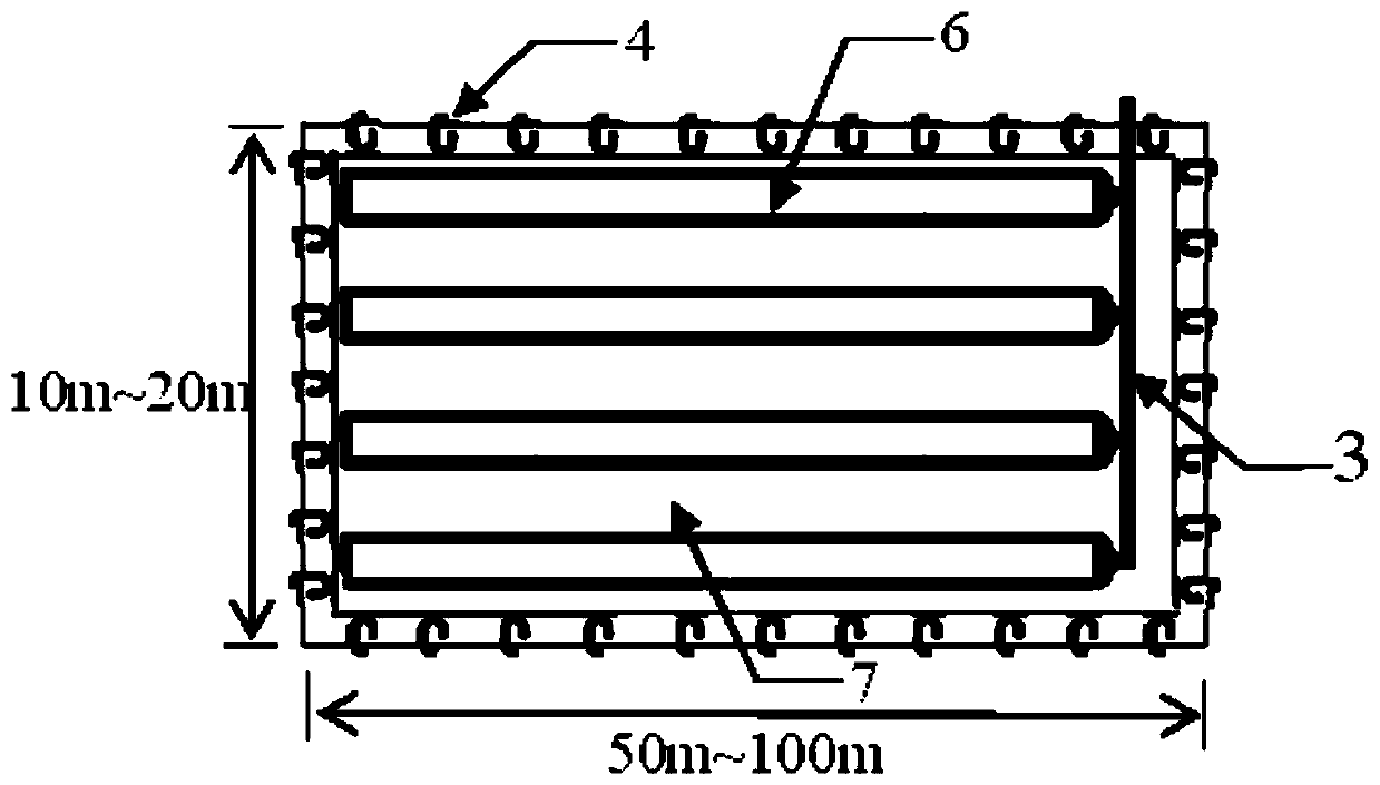
[0049] Divide the silt yard to be treated into N sections (the length of the section is directly determined by the size of the yard, with a width of 10m-20m), and each section is divided into multiple blocks (50m-100m in length and 10m-20m in width);

[0050] In this embodiment, m=2, p=1, that is, the prefabricated geotextile-plastic drainage board reinforced drainage assembly 2 is laid successively on each block of the yard section 1 and section 2, and the reinforcement is completed. Drainage assembly 2 is made up of geotextile 7-horizontal drainage board 6-geotextile 7 from t...

Embodiment 2

[0058] [Example 2] m=3, p=2

[0059] The difference between this embodiment and embodiment 1 is that two sections are poured at one time, and the delay between pouring and laying is still one section.

[0060] The operation table of the present embodiment is as shown in table 2:

[0061] Table 2 The process table when m=3, p=2

[0062]

[0063] In this embodiment, when the flocculated and solidified sludge from section 2n-1 to section 2n is poured, the section 2n+1 has completed the laying of reinforced drainage components, the assembly of vacuum filtration pipes, and the construction of adjacent areas. At this time, the laying of reinforced drainage components in section 2n+2 to section 2n+3, the assembly of vacuum filtration pipes and the locking of reinforced drainage components in adjacent blocks are being carried out. Button stitching work.

Embodiment 3

[0064] [Example 3] m=4, p=2

[0065] The difference between this embodiment and Embodiment 1 is that two sections are poured at one time, and the delay between pouring and laying is two sections.

[0066] The operation table of the present embodiment is as shown in table 3:

[0067] Table 3 Process table when m=4, p=2

[0068]

[0069] In this embodiment, when the flocculated and solidified sludge in section 2n-1 to section 2n is poured, the laying of reinforced drainage components and vacuum filtration pipelines in section 2n+1 to section 2n+2 have been completed. The assembly of the reinforced drainage components in the adjacent blocks and the locking and splicing of the reinforced drainage components in the adjacent blocks are being carried out. Locking splice work for reinforced drainage components.

[0070] Other data combination schemes for m and p can be directly deduced from the general term formula of the present invention and the above-mentioned embodiments, an...


PUM

PropertyMeasurementUnit
Thicknessaaaaaaaaaa
Thicknessaaaaaaaaaa

Abstract

The invention belongs to the field of foundation treatment and silt treatment, and discloses a method for forming an overlying crust on the surface of a dredging silt slurry storage yard and the overlying crust. The method comprises the steps that the surface of the dredging silt slurry storage yard is paved with geotextile-plastic drainage plate reinforced drainage assemblies in a zone-section division and zone-block division mode, dredging silt slurry after wadding solidification treatment is poured onto the geotextile-plastic drainage plate reinforced drainage assemblies in a zone-section gradually-promoted mode, and finally vacuum filtration (namely hydraulic osmosis consolidation) is conducted on the zone blocks completing pouring immediately. According to the method for forming the overlying crust on the surface of the dredging silt slurry storage yard and the overlying crust, the carrying capacity of the surface of the dredging silt slurry storage yard can be obviously improved, and thus the problem that follow-up mechanical equipment cannot enter is effectively solved, in the method for forming the overlying crust on the surface of the dredging silt slurry storage yard, a vacuum filtration-wadding solidification combined method is provided, the advantages of convenient operation, high mechanical construction degree and high construction speed are achieved, the construction work period can be greatly shortened, and the method is suitable for fast turn around treatment of large scale dredging silt slurry storage yards.

Description

technical field [0001] The invention belongs to the fields of foundation treatment and silt treatment, and relates to the technology of forming a working platform on the surface of an ultra-soft stockyard in terms of civil engineering, port waterway engineering, etc., and specifically relates to a method of forming a hard shell layer on the surface of a dredged silt stockyard The method and the hard shell, more specifically, relate to a method and the hard shell for forming a hard shell on the surface of a dredged mud slurry yard by a combined vacuum filtration-flocculation solidification method. Background technique [0002] At present, the construction and maintenance of waterways, ports, and water conservancy and water environment treatment projects such as inland rivers and lakes produce dredged silt up to hundreds of millions of cubic meters (under water), and most of the dredging projects use hydraulic dredging (cutter suction or hydraulic scour) The sludge dredged by ...

Claims


Application Information

Patent Timeline
IPC IPC(8): E02D3/10
CPCE02D3/10
Inventor 章荣军郑耀林乔雅晴屠林伟董超强郑俊杰
Owner HUAZHONG UNIV OF SCI & TECH
Why Eureka
Eureka Blog
Learn More