Anti-vibration bearing device and anti-vibration method

A technology for bearings and inner rings of bearings, applied to bearings, shafts and bearings, rolling contact bearings, etc., can solve the problems of space occupation and poor vibration suppression effect

Pending Publication Date: 2019-09-17
NO 719 RES INST CHINA SHIPBUILDING IND
View PDF0 Cites 1 Cited by
  • Summary
  • Abstract
  • Description
  • Claims
  • Application Information

AI Technical Summary

Problems solved by technology

[0004] The embodiment of the present application provides a vibration suppression bearing device and a vibration suppression method, which solves the technical problem of poor vibration suppression effect and occupying space in the prior art

Method used


Image

  • Anti-vibration bearing device and anti-vibration method
  • Anti-vibration bearing device and anti-vibration method

Examples


Embodiment 1

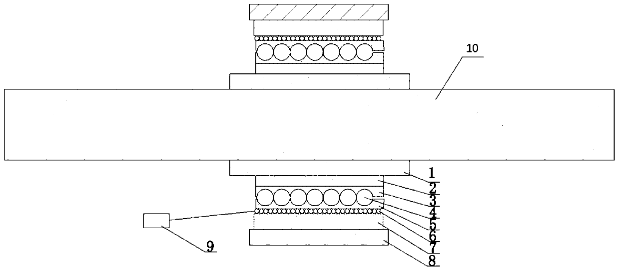
[0040] Such as figure 1 As shown, in this embodiment, a vibration suppression bearing device includes a bearing inner lining 1, an inner permanent magnet 2, a bearing inner ring 3, a ball 4, a bearing outer ring 5, a coil 6, an outer permanent magnet 7, and a bearing outer lining 8 and control system 9; where,

[0041] Specifically, see figure 1 ,

[0042] The inner permanent magnet 2 is fixedly connected to the periphery of the bearing lining 1, and the bearing inner ring 3 is fixedly connected to the periphery of the inner permanent magnet 2;

[0043] The bearing outer lining 8 is fixedly connected to the periphery of the outer permanent magnet 7, the outer permanent magnet 7 is fixedly connected to the periphery of the bearing outer ring 5, and the coil 6 is wound between the bearing outer ring 5 and the bearing outer ring 5. Between the outer permanent magnets 7;

[0044] The ball 4 is movably installed between the bearing inner ring 3 and the bearing outer ring 5, so ...

Embodiment 2

[0073] This embodiment provides a vibration suppression method, which is applied to the bearing device described in Embodiment 1; the method includes:

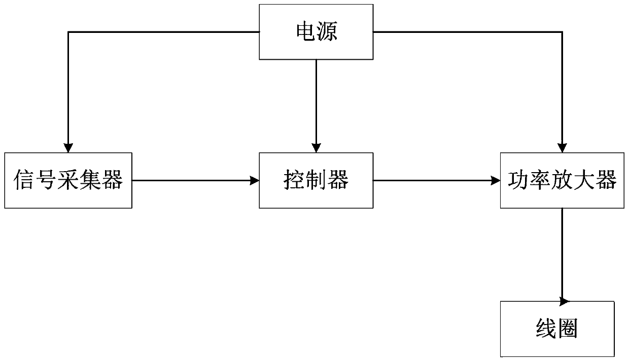
[0074] S101. The signal collector collects vibration signals along the axial direction of the target shaft 10 installed on the bearing to obtain vibration information;

[0075] S102. The controller receives the vibration information, generates a control signal according to the vibration information, and sends it to the power amplifier;

[0076] S103, the power amplifier outputs an alternating current to the coil 6 according to the control signal, so that the coil 6 generates an interaction with the target shaft 10 under the joint action of the inner permanent magnet 2 and the outer permanent magnet 7 Electromagnetic forces in the opposite direction of vibration along the axial direction.

[0077] Specifically, the vibration information in this embodiment includes the direction and amplitude of the vibration

[0078] In this ...


PUM


Abstract

The invention discloses an anti-vibration bearing device, and relates to the technical field of shaft system vibration control. The device comprises a bearing inner lining, an inner permanent magnet, a bearing inner ring, a ball, a bearing outer ring, a coil, an outer permanent magnet, a bearing outer lining and a control system; the inner permanent magnet is fixedly connected to the periphery of the bearing inner lining, the bearing inner ring is fixedly connected to the periphery of the inner permanent magnet, the bearing outer lining is fixedly connected to the periphery of the outer permanent magnet, the outer permanent magnet is fixedly connected to the periphery of the bearing outer ring, the coil is wound between the bearing outer ring and the outer permanent magnet, the ball is movably mounted between the bearing inner ring and the bearing outer ring, and the bearing inner ring and the bearing outer ring can do relative rotation; and the control system is connected with the coil so as to control the coil to generate electromagnetic force for restraining vibration. The technical problem that in the prior art, the anti-vibration effect is poor, and space is occupied is solved.

Description

technical field [0001] The invention relates to the technical field of shafting vibration control, in particular to a vibration suppression bearing device and a vibration suppression method. Background technique [0002] The central shaft of numerous power output equipment and power generation equipment in large-scale power plants and ships plays a key role in connection and transmission. For high-power devices, the shaft system is very long. In order to ensure the centering and safety of the device, it will Bearings are arranged in key parts to play a supporting role. At the same time, the shaft speed of large-scale high-power equipment is generally low and the weight is heavy. In the field of ships, the shaft of a large ship drives the propeller to generate a longitudinal thrust to push the ship forward or backward, and when the propeller is running in water, the uneven water flow will cause longitudinal vibration, and the longitudinal vibration is transmitted to the ship ...

Claims


Application Information

Patent Timeline
IPC IPC(8): F16C19/52F16F15/18
CPCF16C19/527F16F15/002F16F15/18F16F2222/06
Inventor 刘记心章婷夏建超
Owner NO 719 RES INST CHINA SHIPBUILDING IND
Why Eureka
Try Eureka