Energy-saving corn threshing machine

A peeling machine and corn technology, applied in the agricultural field, can solve the problems of inconvenient promotion and implementation, low production efficiency, complex structure, etc., and achieve the effects of easy promotion and implementation, high production efficiency and high peeling quality

Active Publication Date: 2019-09-20
辽宁展华实业有限公司
View PDF7 Cites 6 Cited by
  • Summary
  • Abstract
  • Description
  • Claims
  • Application Information

AI Technical Summary

Problems solved by technology

The device has a complex structure and a large volume, and the corn needs to be put into the device one by one, resulting in a large workload and low production efficiency, which is not convenient for popularization and implementation

Method used


Image

  • Energy-saving corn threshing machine
  • Energy-saving corn threshing machine
  • Energy-saving corn threshing machine

Examples


Embodiment 1

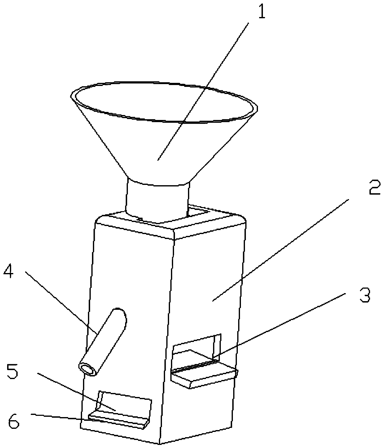
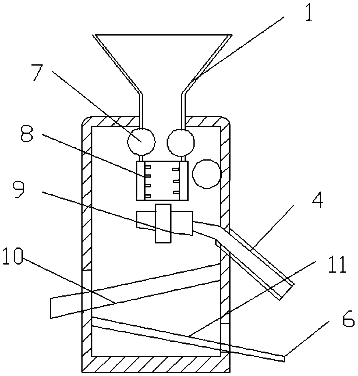
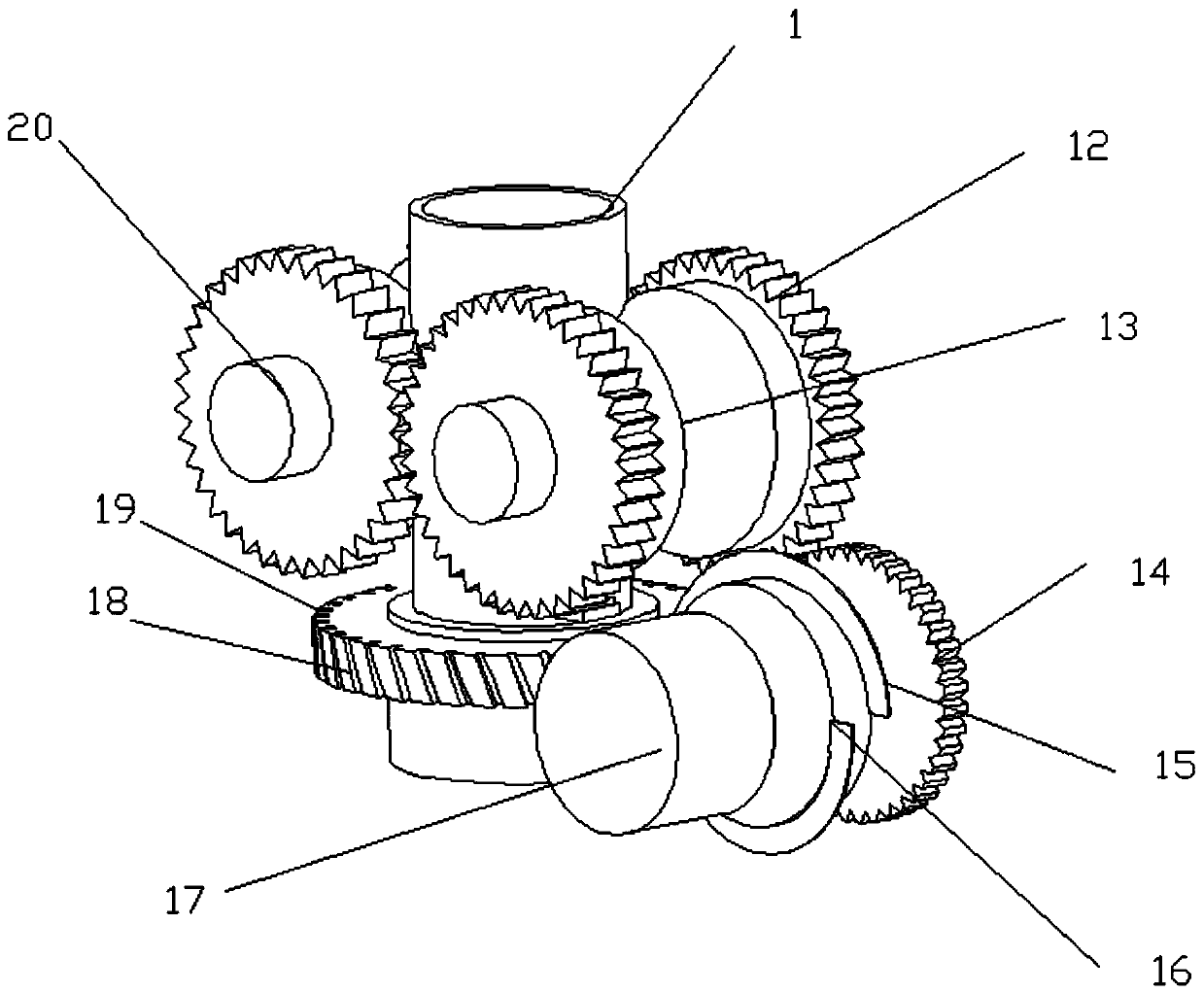
[0026] see Figure 1-5 , an energy-saving corn peeling machine, including a housing 2, a transmission part 7, a peeling cylinder 8 and a separation part 9. The top of the housing 2 is connected with a feed hopper 1, and the corn that needs to be peeled is placed inside the feed hopper 1. The feed hopper 1 is a funnel-shaped structure, and the setting of the feed hopper 1 is convenient for the corn to enter the inside of the housing 2 for separation. The bottom of the feed hopper 1 extends into the inside of the housing 2 , and the inner top of the housing 2 is rotatably provided with a transmission member 7 , and the transmission member 7 extends into the feed hopper 1 . The bottom of feed hopper 1 is connected to the top of shelling cylinder 8 in rotation. The transmission member 7 includes a transmission roller 20 and a driven gear 12, two transmission rollers 20 are arranged horizontally, the two ends of the transmission roller 20 are coaxially fixedly connected with a dri...

Embodiment 2

[0032] On the basis of Embodiment 1, a first sieve plate 10 is provided in the inside of the housing 2 below the separator 9, and a material guide plate 11 is provided at the inner bottom of the housing 2 below the first sieve plate 10, and the material guide The end of the plate 11 is provided with a leaking grain outlet 5 on the side wall of the housing 2, and corn cobs, debris and dropped corn kernels fall on the first sieve plate 10, and the corn kernels and debris pass through the first sieve plate 10 , falls on the material guide plate 11 and is discharged from the leaking grain outlet 5, which avoids the waste of corn grains and improves the recovery rate of stripping. The outer material guide plate 11 of the leakage grain outlet 5 is connected with a second sieve plate 6, and the second sieve plate 6 sieves the corn kernels, removes debris, and improves the cleanliness of the corn kernels.


PUM


Abstract

The invention relates to the technical field of agriculture, and particularly discloses an energy-saving corn threshing machine. The energy-saving corn threshing machine comprises a shell, the top of the shell is communicated with a feeding hopper, transmission pieces are rotatably arranged at the inner top of the shell, the bottom of the feeding hopper is rotatably communicated with the top of a threshing cylinder, each transmission piece comprises a transmission roller and driven gears, every two driven gears are coaxially and fixedly connected to the two ends of the corresponding transmission roller, a driven wheel is coaxially and fixedly arranged on the outer side wall of the threshing cylinder, and several slant grooves are uniformly formed in the driven wheel; a motor is installed inside the shell, a driving wheel and a driving gear are connected to the motor, and spiral blades are fixedly arranged on the outer side wall of the driving wheel, and embedded in the slant grooves; a separating piece is fixedly arranged below the threshing cylinder and communicated with a corn kernel outlet, and a material guiding piece is arranged inside the shell and communicated with a corn cob outlet. The energy-saving corn threshing machine has the advantages of being simple in structure, high in production efficiency and threshing quality, low in production cost, high in threshing recycling rate and cleanliness level, and convenient to popularize and implement.

Description

technical field [0001] The invention relates to the field of agricultural technology, in particular to an energy-saving corn peeling machine. Background technique [0002] Corn is an annual herbaceous plant of the grass family Zea genus. Alias: corn, stick, corn, corn, millet, corn, corn, pearl rice, bract reed, big miliary millet, it is called pearl grain in Northeast Liaoning dialect, barley kernel in Chaozhou dialect, corn in Cantonese, and fan in Hokkien dialect. wheat. Maize is an annual monoecious cross-pollinated plant with tall plants and strong stems. It is an important food crop and feed crop. It is also the crop with the highest total output in the world. Its planting area and total output are second only to rice and wheat. Corn has always been known as a longevity food, rich in protein, fat, vitamins, trace elements, cellulose, etc., and has great potential for developing high-nutrition, high-biological function foods. However, due to its complex heredity and ...

Claims


Application Information

Patent Timeline
Patent Type & Authority Applications(China)
IPC IPC(8): A01F11/06A01F12/18A01F12/44
CPCA01F11/06A01F12/18A01F12/446Y02P60/14
Inventor 崔锐
Owner 辽宁展华实业有限公司
Why Eureka
Try Eureka