Rotary electric machine system and vehicle

A technology for rotating electric machines and vehicles, which is applied to motor vehicles, vehicle components, hybrid vehicles, etc., and can solve problems such as difficulty in suppressing the cost of rotating electric machine units, ensuring the performance of rotating electric machine units and suppressing costs, etc., to achieve cost suppression and drag loss Reduced effect

Inactive Publication Date: 2019-09-24
HONDA MOTOR CO LTD
View PDF7 Cites 0 Cited by
  • Summary
  • Abstract
  • Description
  • Claims
  • Application Information

AI Technical Summary

Problems solved by technology

[0009] However, it is difficult to suppress the cost of the rotating electrical machine unit in the case of reducing the drag loss by improving the steel plate material, reducing the amount of magnets, etc.
Therefore, in this method, it is difficult to ensure the performance of the rotating electric machine unit and suppress the cost

Method used


Image

  • Rotary electric machine system and vehicle
  • Rotary electric machine system and vehicle
  • Rotary electric machine system and vehicle

Examples


no. 1 approach

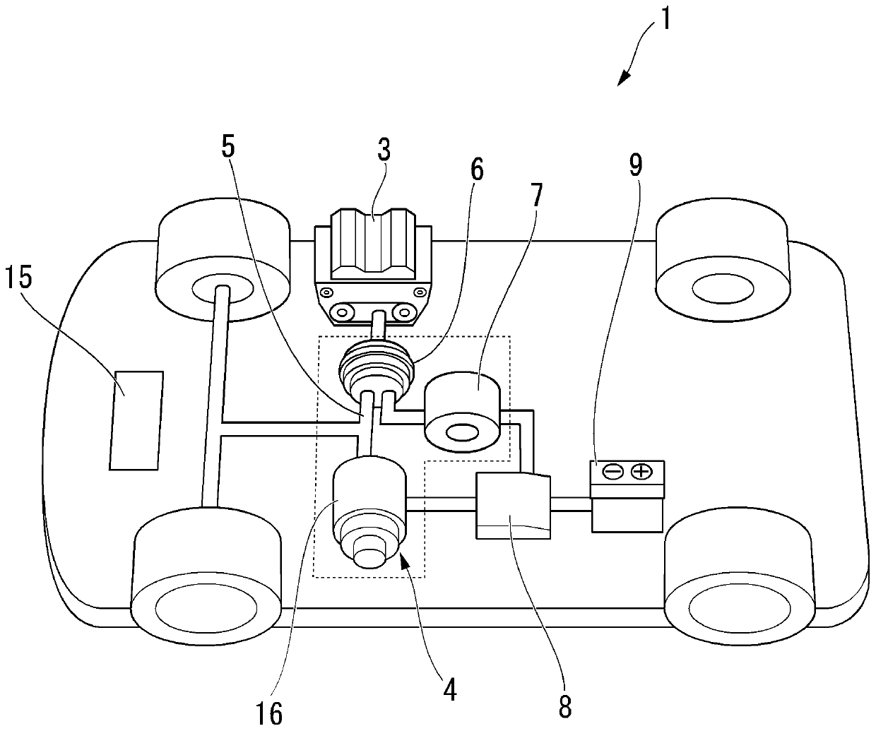
[0045] Such as figure 1 As shown, a hybrid vehicle 1 (vehicle) is provided with an internal combustion engine 3 and a rotary electric machine 16 , and travels with the driving force of at least one of the internal combustion engine 3 and the rotary electric machine 16 depending on the running state. That is, the hybrid vehicle 1 includes an internal combustion engine 3 , a rotary electric machine system 4 , a drive shaft (pedal shaft) 5 , a power distribution mechanism 6 , a generator 7 , an inverter 8 , and a battery 9 .

[0046] When the hybrid vehicle 1 is running, the internal combustion engine 3 , the rotary electric machine 16 , the generator 7 , the inverter 8 , and the like generate heat. Therefore, the hybrid vehicle 1 includes, for example, a refrigerant cooling mechanism 17 for cooling the rotary electric machine 16 and the generator 7 (see Figure 5 ).

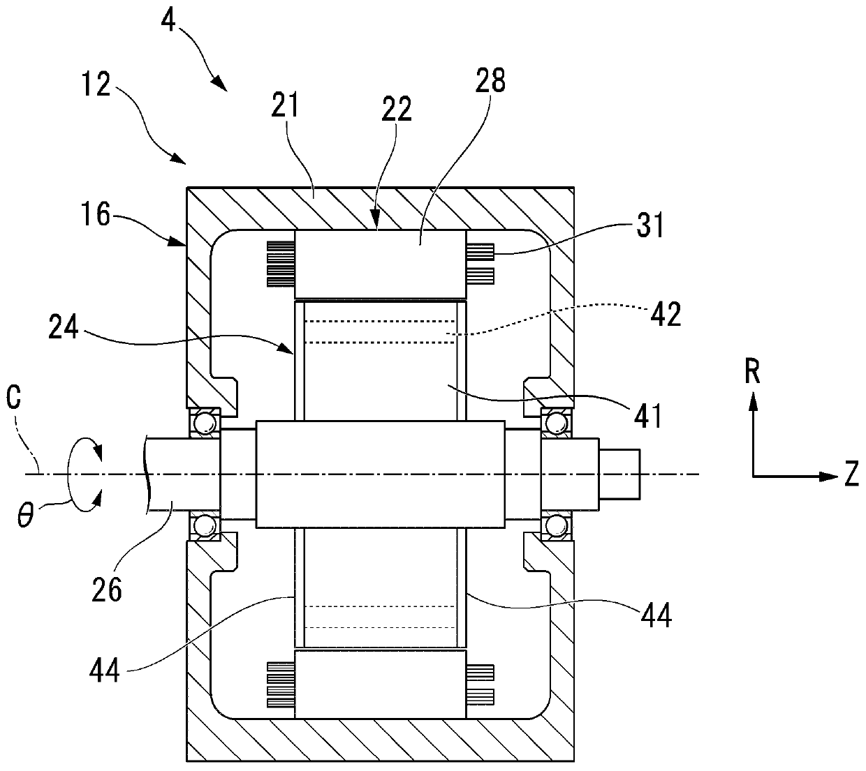
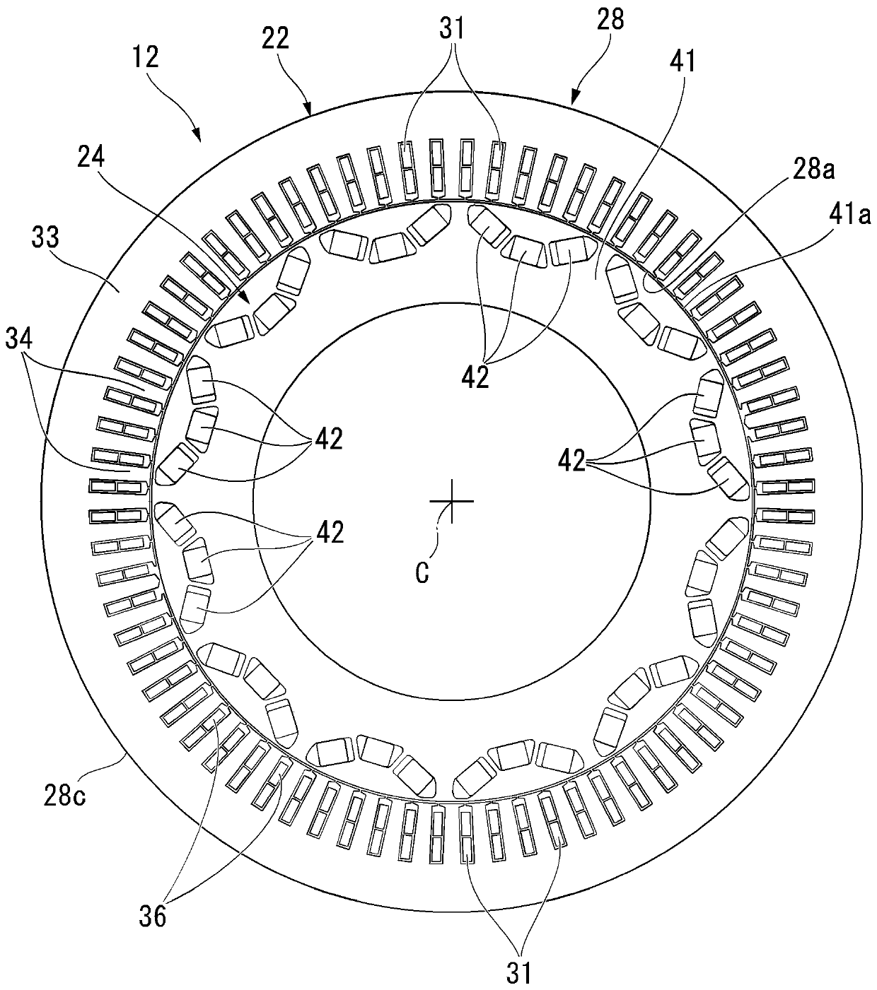
[0047] Such as figure 2 , image 3 As shown, the rotating electrical machine system 4 includes a rotating e...

no. 2 approach

[0124] Such as Figure 12 As shown, a hybrid vehicle 100 (vehicle) includes an internal combustion engine 101 , a rotating electric machine 102 , a drive shaft (pedal shaft) 103 , a transmission (planetary gear) 104 , and a generator 105 . The hybrid vehicle 100 runs with an engine instead of a motor in order to efficiently use energy during high-speed cruising, for example. In this state, when the rotating electric machine 102 is directly connected to the drive shaft 103 , the rotating electric machine 102 is rotated by the internal combustion engine 101 , and no-load loss (drag loss) occurs in the rotating electric machine 102 .

[0125]According to the hybrid vehicle 100 , by raising the temperature of the stator core of the rotary electric machine 102 , iron loss generated in the stator core can be suppressed. In this way, the drag loss of the rotary electric machine system can be reduced in the hybrid vehicle 100 by utilizing the phenomenon that the iron loss (eddy curre...

no. 3 approach

[0128] Such as Figure 13 As shown, a hybrid vehicle 110 (vehicle) includes an internal combustion engine 111 , a rotary electric machine 112 , a drive shaft (pedal shaft) 113 , an inverter 114 , a battery 115 , and a generator 116 . Hybrid vehicle 110 runs on an engine instead of a motor in order to efficiently use energy during high-speed cruising, for example. In this state, when rotating electric machine 112 is directly connected to drive shaft 113 , rotating electric machine 112 is driven to rotate by internal combustion engine 111 , and no-load loss (drag loss) occurs in rotating electric machine 112 .

[0129] According to the hybrid vehicle 110 , by increasing the temperature of the stator core of the rotary electric machine 112 , it is possible to suppress the iron loss generated in the stator core. In this way, the drag loss of the rotary electric machine system can be reduced in the hybrid vehicle 110 by utilizing the phenomenon that the iron loss (eddy current los...


PUM


Abstract

The invention provides a rotary electric machine system and a vehicle in which a drag loss is able to be reduced and also costs are able to be minimized. The rotary electric machine system comprises a rotary electric machine unit, a temperature adjustment unit and a control unit. The rotary electric machine unit is provided with a rotary electric machine and a temperature detection unit. The rotary electric machine is provided with a stator core on which a coil is wound, and a rotor with a magnet. The temperature adjustment unit increases the temperature of the stator core. When a rotational speed of the rotary electric machine is in a predetermined high-speed rotation state, in a case in which the temperature detected by the temperature detection unit is less than a predetermined value, the control unit controls the temperature control unit to increase the temperature of the rotary electric machine.

Description

technical field [0001] The present invention relates to a rotating electric machine system and a vehicle. Background technique [0002] As a rotary electric machine for driving a vehicle, a magnet motor (in particular, an IPM (Interior Permanent Magnet) in which a magnet is embedded in a rotor) is generally used because of its high efficiency. In the case of a hybrid electric vehicle (HEV) or a plug-in hybrid electric vehicle (PHEV), during high-speed cruising, energy management is considered in order to use energy efficiently, and engine running is generally performed without motor driving. In this state, in the case of a vehicle in which the rotating electric machine is directly connected to the drive shaft, the rotating electric machine is driven to rotate, and no-load loss (hereinafter referred to as drag loss) occurs. In order to eliminate this loss, there is known a vehicle equipped with a clutch that disconnects the rotary electric machine from the drive shaft. Howe...

Claims


Application Information

Patent Timeline
Patent Type & Authority Applications(China)
IPC IPC(8): H02K11/25H02K1/16H02K1/27H02K9/19
CPCH02K11/25H02K1/16H02K1/274H02K9/19H02K11/30H02K15/125B60K6/445B60K6/46B60K6/48B60K2006/4825B60K2006/4808B60K6/26Y02T10/62B60Y2400/60B60Y2200/92B60Y2306/05H02K9/00
Inventor 糸山辽介壹岐友贵
Owner HONDA MOTOR CO LTD
Why Eureka
Try Eureka