Construction method of water intaking pipes

A construction method and technology for water intake pipes, applied in water conservancy projects, artificial islands, water supply devices, etc., can solve problems such as inability to guarantee construction quality, expensive machinery and equipment, and inability to isolate water, so as to ensure the quality of welding, shorten the docking time, The effect of ensuring the quality of joints

Inactive Publication Date: 2019-09-27
CHINA HUAYE GROUP +1
View PDF3 Cites 7 Cited by
  • Summary
  • Abstract
  • Description
  • Claims
  • Application Information

AI Technical Summary

Problems solved by technology

[0003] The water area where the water is drawn is generally abundant in water, and most of the installation and construction of the water intake pipeline cannot be carried out in isolation from the water. There are two construction methods for the existing water intake pipes: one is to use manual welding of the pipes, and then the overall hoisting and sinking method into the water; welding A good pipe is too heavy when it is long, and it needs to be hoisted by a large ship. Moreover, the elevation of the water intake pipe is different. When the water intake pipe enters the shore, the elevation becomes higher and the coordinates change, so that the water intake pipe cannot be hoisted as a whole; The pipe diameter is large, the pipe wall is thick, the underwater welding technology is immature, and the quality cannot be guaranteed; and the underwater welding labor, equipment and equipment are extremely expensive, the welding speed cannot meet the requirements of the construction period, the construction is difficult and the construction quality cannot be guaranteed

Method used


Image

  • Construction method of water intaking pipes
  • Construction method of water intaking pipes
  • Construction method of water intaking pipes

Examples


Embodiment Construction

[0025] In order to further illustrate the technical means and effects of the present invention for solving technical problems, the present invention will be further described in detail below in conjunction with the accompanying drawings and specific embodiments. It should be noted that the provided accompanying drawings are schematic and mutually exclusive They are not drawn to scale or scale, and therefore the drawings and specific examples are not intended to limit the scope of protection claimed by the invention.

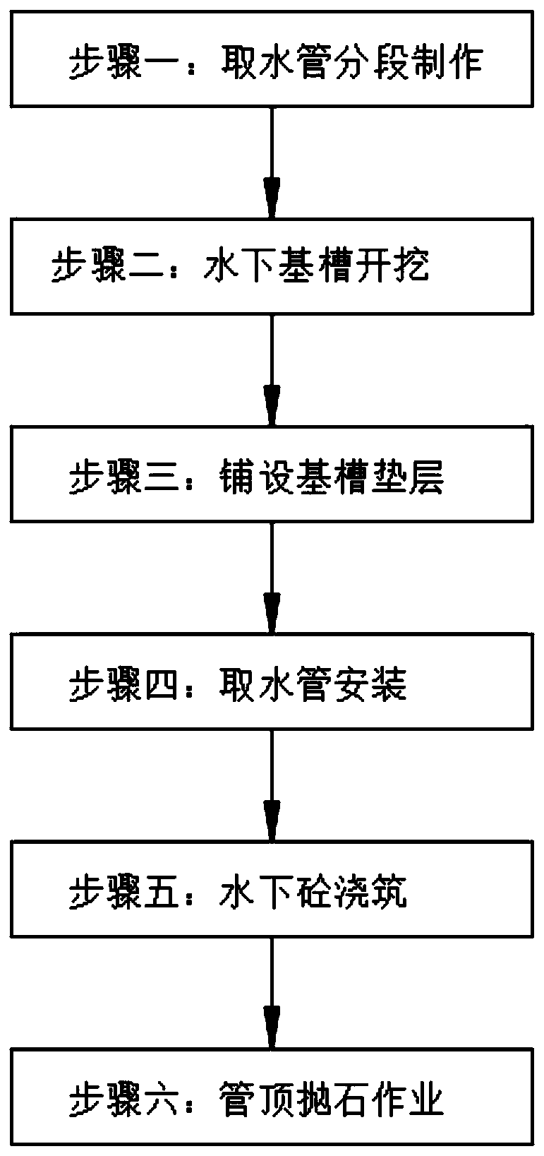
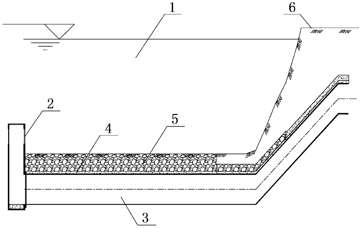
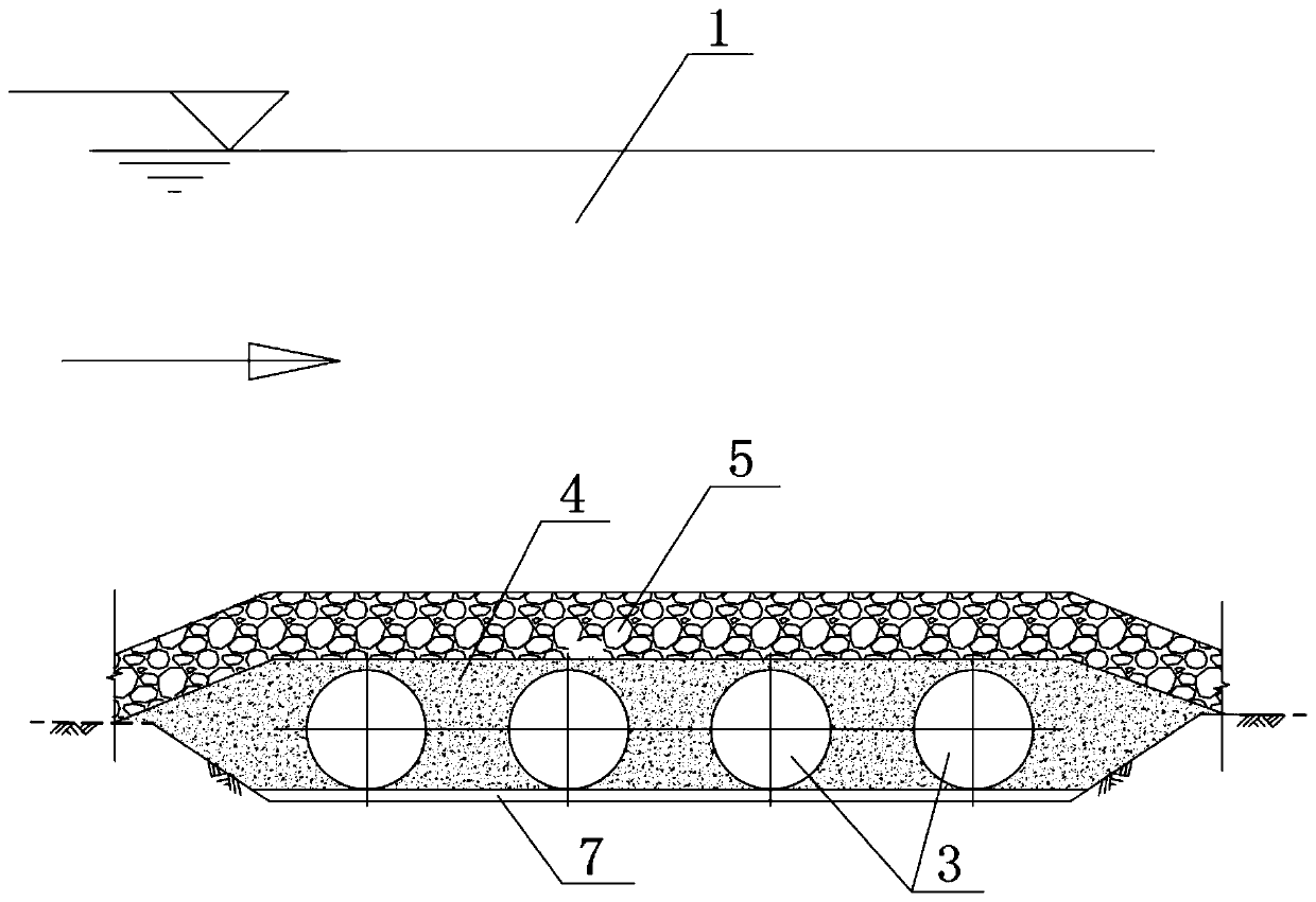
[0026] Such as figure 1 The construction method of the water intake pipe of the present invention shown, carry out figure 2 and image 3 The construction of the shown water intake pipeline includes the following steps:

[0027] Step 1: The water intake pipe 3 is made in sections; the water intake pipe 3 is made of Q235B steel pipe, the outer diameter of the water intake pipe is 3020mm, and the wall thickness is 30mm. To protect the automatic welding process, ...


PUM


Abstract

The invention belongs to the technical field of underwater pipeline installation and construction, and discloses a construction method of water intaking pipes. The construction method of the water intaking pipes comprises five steps that step 1, the water intaking pipes are manufactured in section; step 2, an underwater foundation trench is excavated; step 3, a foundation trench cushion layer is laid; step 4, the water intaking pipes are installed; step 5, underwater concrete is poured; and no sequence of time exists between the step 1 and the step 2 as well as between the step 1 and the step 3. According to the construction method of the water intaking pipes, the water intaking pipelines are adopted in section on shore, carbon dioxide gas automatic shielded-welding welding and anti-corrosion processing treatment are adopted, the processed pipelines are transported and lifted in section, immersed tubes are installed, the underwater connection of all pipe sections adopts a Huff joint form, underwater welding and the demand for large lifting ships can be avoided, the quality of manufacturing welding and connection is ensured, and the efficiency can be greatly improved; and the construction time is shortened, according to the construction method, no more labor and space on site are occupied, planning in advance can be carried out, and the cost is saved.

Description

technical field [0001] The invention belongs to the technical field of installation and construction of underwater pipelines, in particular to a construction method for water intake pipes. Background technique [0002] Most cities in my country have the phenomenon of substandard drinking water sources and insufficient water sources. In order to ensure the quality of water intake, the water intake is set at a place far away from the shore where the water quality is not easily affected. For example, water is taken from the center of a river. In this way, it is necessary to divert water to the pump room interface through an artesian pipe made of large-diameter steel pipes under the river. It is transported to major pumping stations and water plants for treatment to ensure the quality of drinking water. [0003] The water area where the water is drawn is generally abundant in water, and most of the installation and construction of the water intake pipeline cannot be carried out...

Claims


Application Information

Patent Timeline
Patent Type & Authority Applications(China)
IPC IPC(8): E03B3/00E02D29/00F16L1/16
CPCE02D29/00E03B3/00F16L1/16
Inventor 陈爱坤吕延京
Owner CHINA HUAYE GROUP
Why Eureka
Try Eureka