
Integrated super-gravity separation device

A separation device and super-gravity technology, which are applied in combination devices, separation methods, dispersed particle separation, etc., can solve the problems of low separation efficiency of super-gravity rotating packed bed, gas easily entrained liquid, solid particles, good or bad effect, etc. Compact structure, improved flood point, good effect

Pending Publication Date: 2019-10-01
成都市珑熙科技有限公司
View PDF0 Cites 1 Cited by
  • Summary
  • Abstract
  • Description
  • Claims
  • Application Information

AI Technical Summary

Problems solved by technology

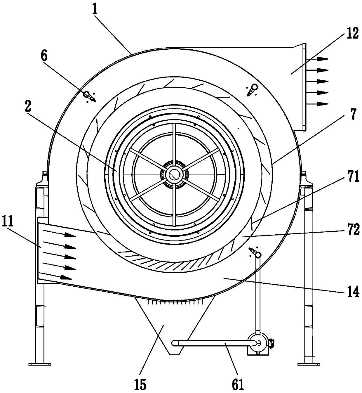
[0004] The technical problem to be solved and the technical task proposed by the present invention are to improve the existing technology and provide an integrated supergravity separation device to solve the problem of low separation efficiency and poor effect of the high gravity rotating packed bed in the current technology, and the gas is easy to entrain liquid , the problem of solid particles

Method used


Image

  • Integrated super-gravity separation device
  • Integrated super-gravity separation device
  • Integrated super-gravity separation device

Examples


Embodiment 1

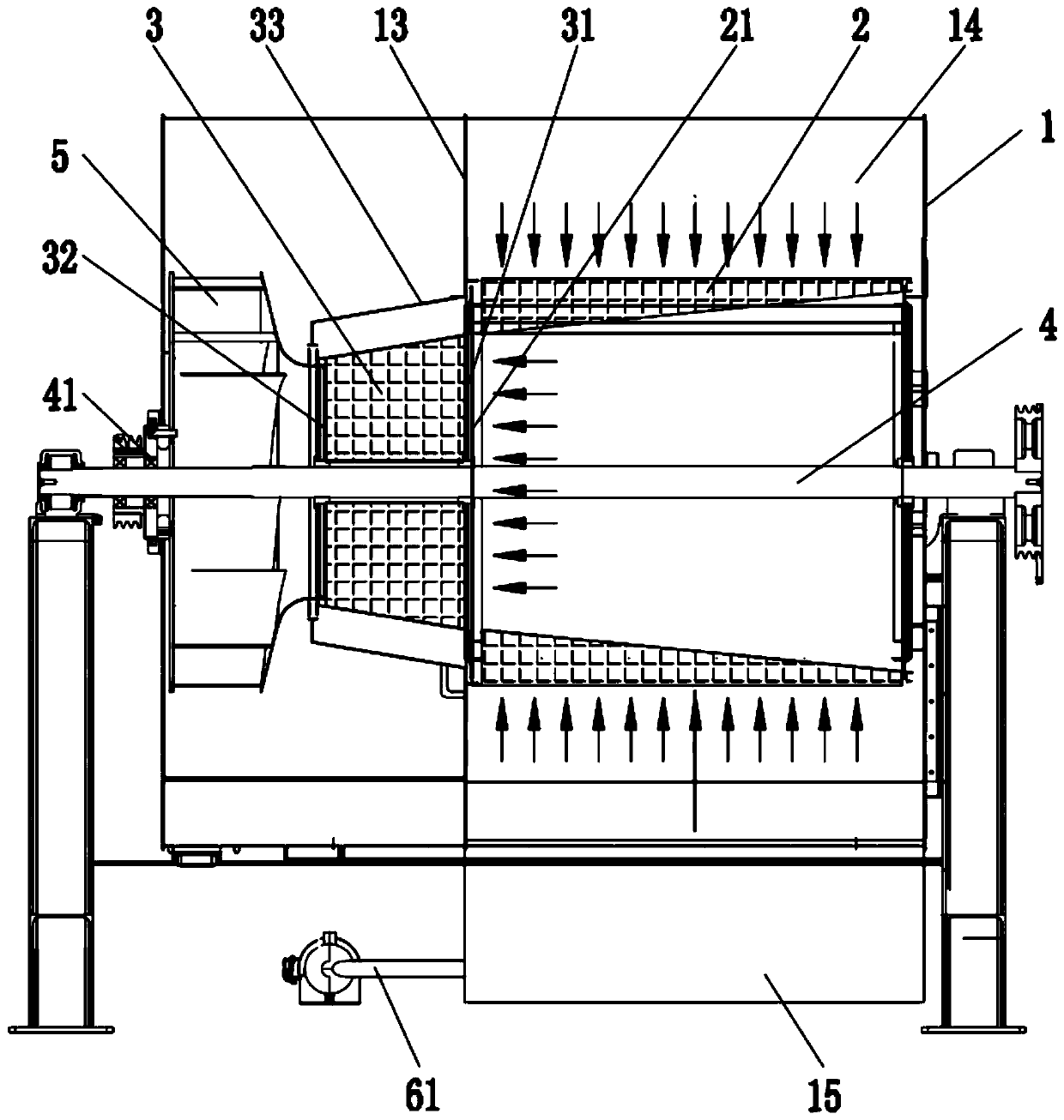
[0049] Such as Figure 1 to Figure 4 As shown, an integrated supergravity separation device mainly includes a housing 1, a counter-current rotating packing layer 2 and a cross-flow rotating packing layer 3; the housing 1 is provided with an air inlet 11 and an air outlet 12; the counter-current rotating packing layer 2 and the The cross-flow rotating packing layer 3 is both rotatably arranged in the housing 1; the air inlet 11 is connected to the circumferential peripheral area of ​​the counter-current rotating packing layer 2, and the axial center gas phase outlet port 21 of the counter-current rotating packing layer 2 is connected to the cross-flow The axial inlet port 31 of the rotating packing layer 3 and the axial gas phase outlet port 32 of the cross-flow rotating packing layer 3 communicate with the air outlet 12 .

[0050] Specifically, the counter-current rotating packing layer 2 and the cross-flow rotating packing layer 3 are coaxially connected to the main rotating ...

Embodiment 2

[0066] Such as Figure 5 As shown, the difference from Embodiment 1 is that both ends of the rotating axial direction of the counter-current rotating packing layer 2 are provided with an axial central gas phase outlet port 21, and the cross-flow rotating packing layer 3 rotates when the counter-current rotating packing layer 2 There is one at both ends of the axial direction, and two air outlets 12 are provided on the housing 1 and communicate with the axial gas phase outlet port 32 of a counter-current rotating packing layer 2 respectively, and the fan 5 is also provided in each counter-current rotating packing layer. Two axial gas phase outlets 32 are provided respectively, and the air inlet 11 on the casing 1 is arranged at the middle position close to the rotation axis of the counter-current rotating packing layer 2, and the dust-laden gas is rotated from the counter-current rotating packing layer 2 to the middle area of ​​the axial direction. The flow is divided to both e...

Embodiment 3

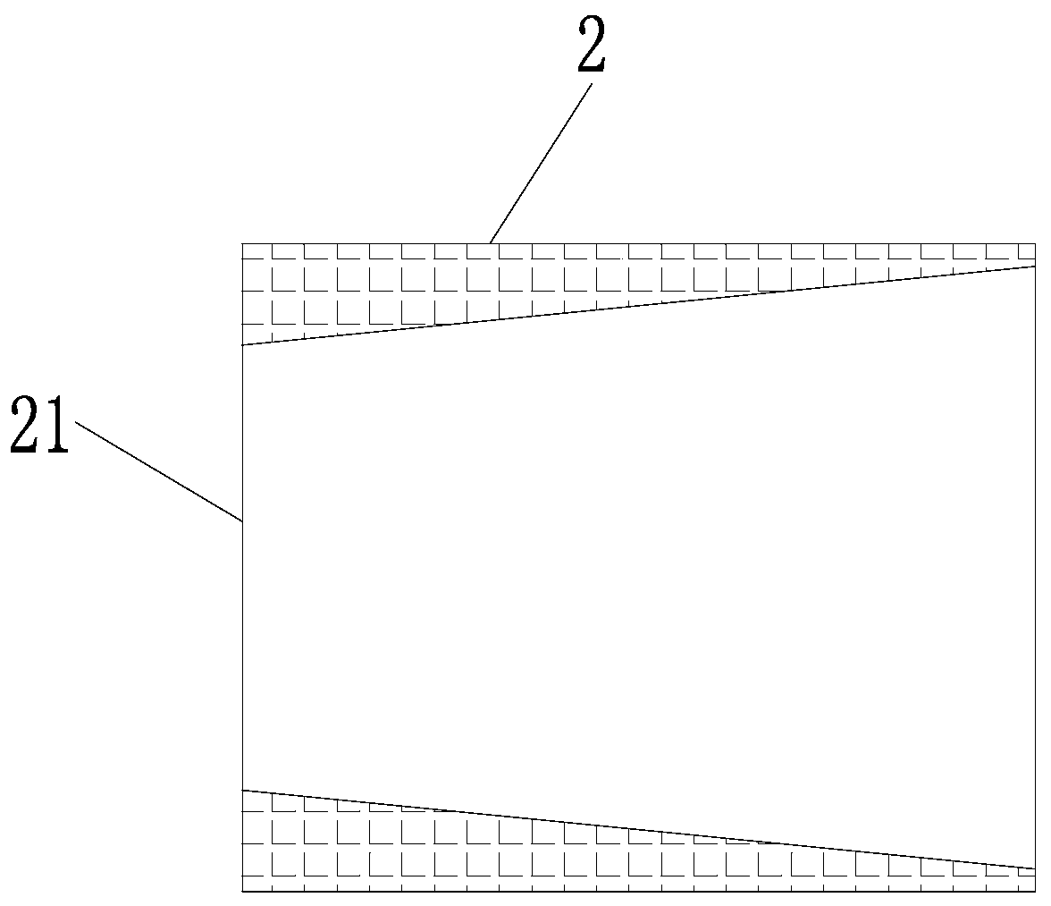
[0068] Such as Figure 6 As shown, the difference from Example 1 is that the packing density of the counter-current rotating packing layer 2 increases toward the axial center gas phase outlet port 21 of the counter-current rotating packing layer 2 along the rotational axis of the counter-current rotating packing layer 2, along the The radial thickness of the counter-current rotating packing layer 2 on the rotating axis of the counter-current rotating packing layer 2 is uniform, while the packing density changes stepwise along the rotating axis of the counter-current rotating packing layer 2. The counter-current rotating packing layer 2 is composed of porous Packing structure, the filler porosity near the axial center gas phase outlet end 21 is getting smaller and smaller, thereby increasing the air intake resistance of the countercurrent rotating packing layer 2 on the axial center gas phase outlet end 21 side in the axial direction, and solving the problem of The axial uneven...


PUM


Abstract

The invention discloses an integrated super-gravity separation device. The device comprises a shell, a counter-current rotating packing layer and a cross-current rotating packing layer, wherein the shell is provided with an air inlet and an air outlet; the counter-current rotating packing layer and the cross-current rotating packing layer are rotationally arranged in the shell; the air inlet is communicated to the circumferential peripheral region of the counter-current rotating packing layer, and the axial central gas-phase outlet end of the counter-current rotating packing layer is communicated to the axial inlet end of the cross-current rotating packing layer; the axial gas-phase outlet end of the cross-current rotating packing layer is communicated with the air outlet. According to theintegrated type super-gravity separation device, a traditional counter-current rotating packing bed and a cross-current rotating packing bed are integrated into a whole, the structure is compact, theoccupied space is small, dust-containing gas is subjected to two-stage super-gravity separation treatment, the homogenization and mixing capacity is good, the flux is large, the resistance of the counter-current rotating packing layer is reduced under the same unit flux, the flooding point is increased, dust in the gas is effectively separated and removed, the dust removal efficiency is high, theeffect is good, and the cleanliness of the treated gas is improved.

Description

technical field [0001] The invention relates to the technical field of gas-solid separation, in particular to an integrated supergravity separation device. Background technique [0002] High-gravity separation technology uses high-gravity conditions to strengthen the relative velocity and mutual contact between phases, and utilizes centrifugal force to strengthen transfer and microscopic mixing to achieve efficient multi-phase reaction and separation. The high-gravity rotating packed bed is driven by the internal rotor to rotate the packing layer at a high speed, and the centrifugal force generated cuts the liquid into smaller micro-elements, which greatly enhances the mass transfer efficiency. Dispersion, which is conducive to the infiltration of dust, has a strong ability to capture dust in the gas. When the dust-laden gas passes through the gaps in the packing layer filled with liquid micro-elements rotating at high speed, the inertial settling ability of the dust is enha...

Claims


Application Information

Patent Timeline
Patent Type & Authority Applications(China)
IPC IPC(8): B01D45/00B01D45/12B01D45/04B01D45/18B01D50/00
CPCB01D45/00B01D45/12B01D45/04B01D45/18B01D50/40
Inventor 肖仁旺杨银
Owner 成都市珑熙科技有限公司
Learn More