Normal-temperature liquid phase catalysis reduction denitration device

A liquid-phase catalysis and liquid-phase catalyst technology, applied in the field of flue gas purification, can solve the problems of poor denitration effect and high denitration cost, and achieve the effects of fast reaction rate, low denitration temperature and strong activity

Inactive Publication Date: 2019-10-01
湖北陆盛环保工程有限公司
View PDF3 Cites 0 Cited by
  • Summary
  • Abstract
  • Description
  • Claims
  • Application Information

AI Technical Summary

Problems solved by technology

[0004] The invention provides a liquid phase catalytic reduction denitrification device at room temperature with simple structure, low denitrification cost, low denitrification temperature and good denitrification effect, so as to solve the technical problems of high denitrification cost and poor denitrification effect in the prior art

Method used


Image

  • Normal-temperature liquid phase catalysis reduction denitration device

Examples


Embodiment Construction

[0031] The following will clearly and completely describe the technical solutions in the embodiments of the present invention with reference to the accompanying drawings in the embodiments of the present invention. Obviously, the described embodiments are only some, not all, embodiments of the present invention.

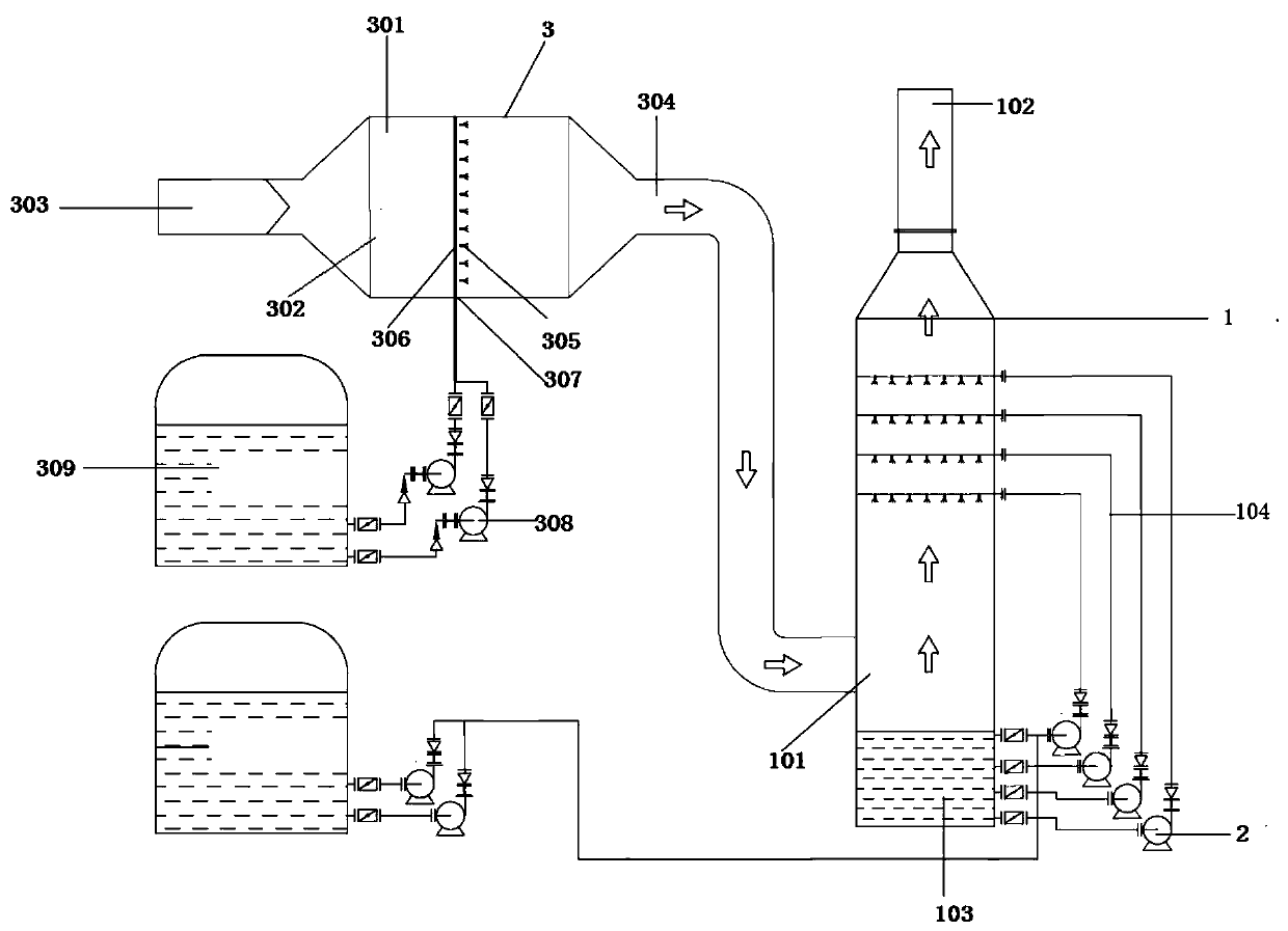
[0032] refer to figure 1 , a normal temperature liquid-phase catalytic reduction denitrification device, including a reduction tower 1, a reduction system and a catalytic system 3, the reduction tower 1 is provided with an air inlet 101 and an air outlet 102, and the air inlet 101 is connected to the output end of the catalytic system 3 , and in the reduction tower 1 built-in spraying device 104, the input end of the spraying device 104 is connected with the reduction system and the bottom of the reduction tower 1 respectively; The gas port 101 is connected, the catalytic converter 301 has a built-in atomizing spray gun 305, and the atomizing spray gun 305 is externa...


PUM


Abstract

The invention relates to the technical field of flue gas purification, in particular to a normal-temperature liquid phase catalysis reduction denitration device. Through a reduction tower and a catalytic system, industrial flue gas containing SO2 and NOx enters a catalysis device through a flue, a liquid-phase catalyst is atomized by an atomization spray gun in the catalysis device and sufficiently mixed with the industrial flue gas, and therefore when making contact with the liquid-phase catalyst, NOx molecules in the flue gas are captured and subjected to molecule chain breaking, N.O+ is formed, and a denitration catalysis reaction is completed; the flue gas after the denitration catalysis reaction is completed enters the reduction tower, a spraying device in the reduction tower conveysthe liquid-phase catalyst in a reduction system to the top of the reduction tower, the flue gas moves from bottom to top, the reduction agent moves from top to bottom, and therefore convection impacting is formed, the flue gas is sufficiently mixed with the reduction agent, and a denitration reaction is completed.

Description

technical field [0001] The invention relates to the technical field of flue gas purification, in particular to a normal-temperature liquid-phase catalytic reduction denitrification device. Background technique [0002] The emission of sulfur dioxide and nitrogen oxides per unit of GDP in my country is several times that of developed countries, which has exceeded the self-purification capacity of my country's atmospheric environment; statistics show that with the development of technological economy and the deepening of the concept of circular economy, the ammonia method highlights its advantages. High denitrification efficiency without producing CO 2 ; However, the existing denitrification devices have ammonia escape and high energy consumption, which need to be solved urgently. [0003] At present, the vast majority of flue gas denitrification methods use SNCR and SCR methods for denitration; SNCR denitrification is to spray ammonia and other reducing agents into the boiler...

Claims


Application Information

Patent Timeline
Patent Type & Authority Applications(China)
IPC IPC(8): B01D53/90B01D53/56B01D53/75
CPCB01D53/75B01D53/8631B01D53/90B01D2251/2062B01D2258/0283
Inventor 杨大颖熊伟周坤明杨大豪
Owner 湖北陆盛环保工程有限公司
Why Eureka
Try Eureka