Check patentability & draft patents in minutes with Patsnap Eureka AI!

Duplex tooth production device of high-precision speed reducer for robot and application method thereof

A production device, a technology of double gears, applied in the field of machinery, can solve the problems of lack of assembly conditions, reduced performance of the reducer, and inability to meet the use requirements, etc., to ensure machining accuracy, eliminate phase angle errors, and eliminate tooth alignment errors. Effect

Active Publication Date: 2019-10-01
BEIJING INSTITUTE OF TECHNOLOGYGY
View PDF6 Cites 1 Cited by
  • Summary
  • Abstract
  • Description
  • Claims
  • Application Information

AI Technical Summary

Problems solved by technology

[0005] In the existing schemes, gear alignment tooling or gear alignment machines are generally used, and only one set of double teeth alignment can be completed at a time, while the actual planetary reducer uses at least 3 or more double teeth, and the transmission alignment process, due to separate processing There must be a certain error in the gear itself. The error of each pair of double teeth is random, and there is no condition for grouping assembly according to the error level when reassembling, which will cause the overall performance of the reducer to decline and cannot meet the use requirements.

Method used


Image

  • Duplex tooth production device of high-precision speed reducer for robot and application method thereof
  • Duplex tooth production device of high-precision speed reducer for robot and application method thereof
  • Duplex tooth production device of high-precision speed reducer for robot and application method thereof

Examples


Embodiment 1

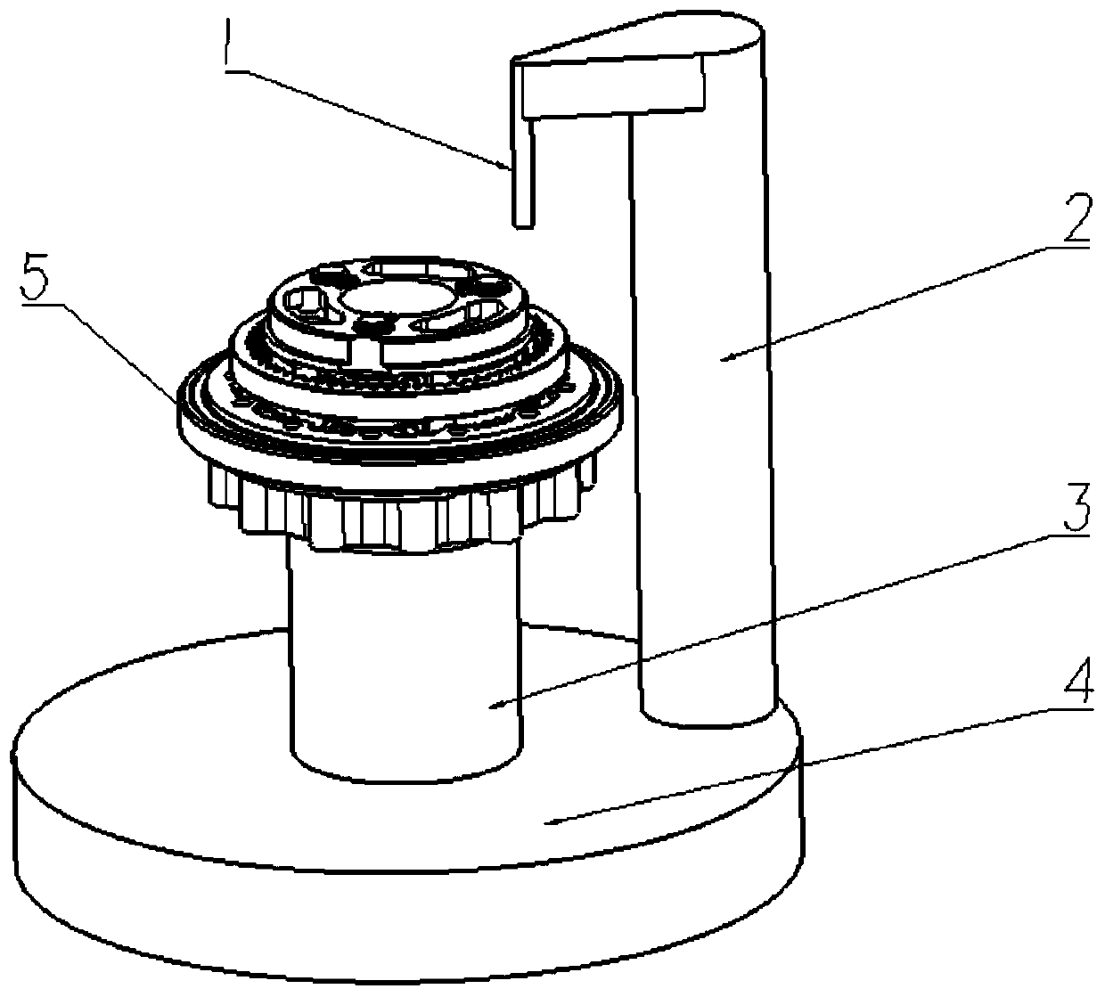
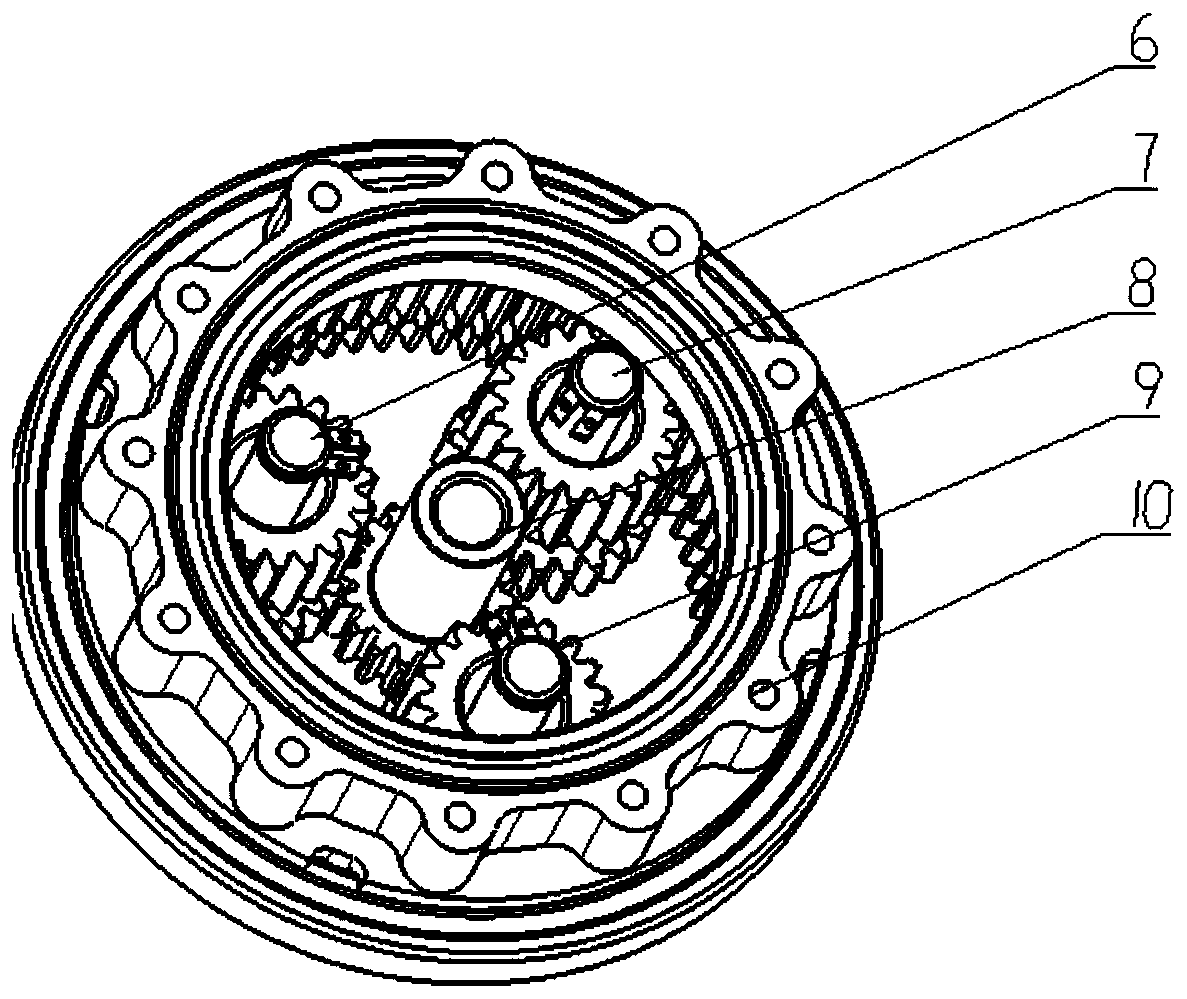
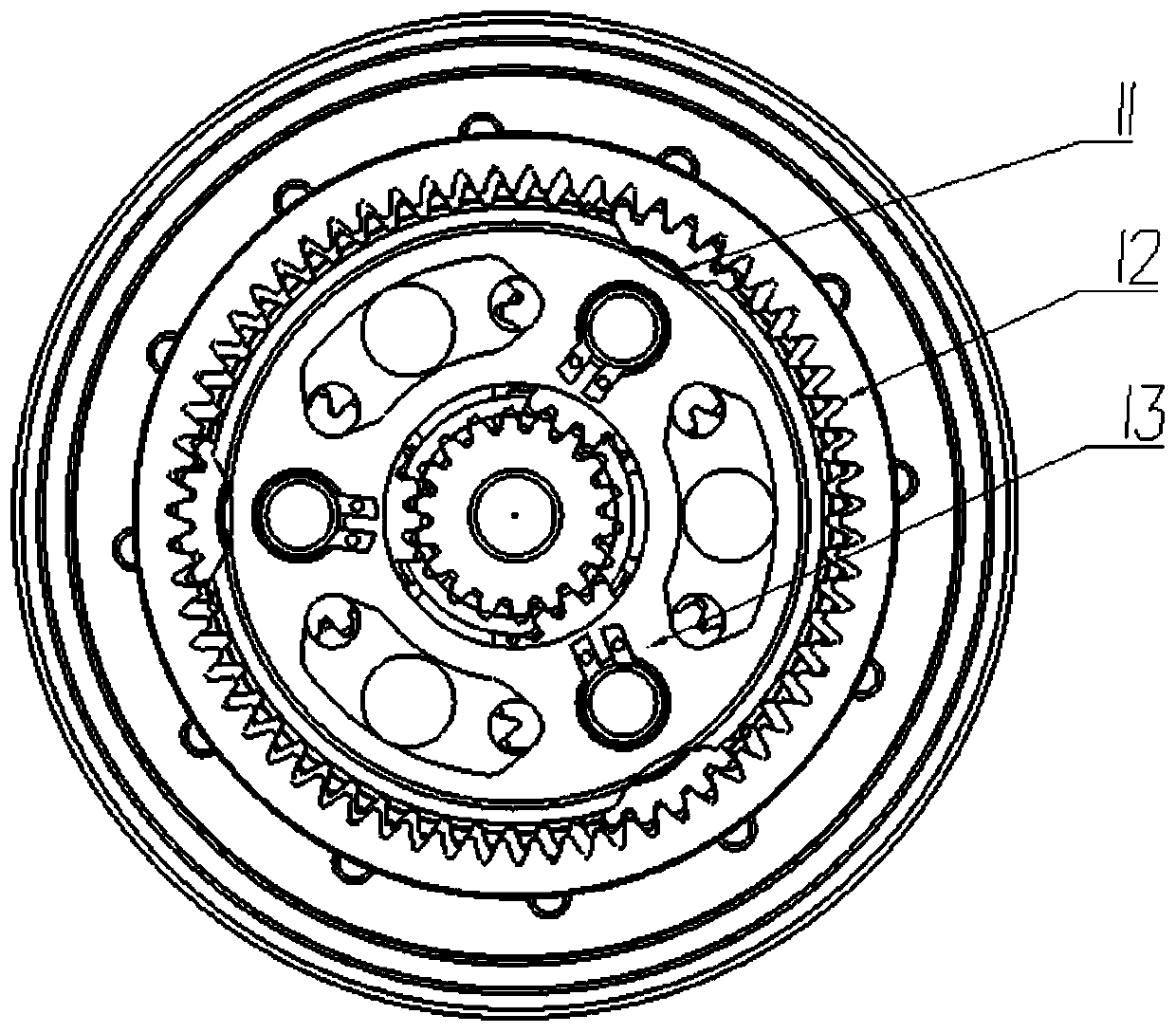
[0036] Embodiment 1: first install the double gear A6, double gear B7 and double gear C9 inside the reducer main body 5, and install the rotating shaft of the central gear 8 of the reducer main body 5 on the slewing mechanism 3, and then install the double gear The rotating shafts of tooth A6, double tooth B7 and double tooth C9 are installed on the turntable 13. When in use, the turntable 13 and the output ring gear 10 are first fixed, and a constant torque is provided through the rotary mechanism 3. This torque needs to be Ensure that the two gears of each set of dual gears can rotate relative to each other, because the two gears of the dual gears are in transition fit with the rotating shaft, and can rotate relative to each other when the torque reaches a certain level. During the rotation, each gear contacts The matching parts are in full contact, and the double gear A6, double gear B7 and double gear C9 evenly distribute the torque of the central gear 8, and the double gea...


PUM


Abstract

The invention provides a duplex tooth production device of a high-precision speed reducer for a robot and an application method thereof. The device comprises a laser welding device, a laser rotating support, a rotating mechanism, a rotating platform and a speed reducer main body, wherein the center of a central gear is fixedly connected with a rotating shaft; and a duplex gear A, a duplex gear B and a duplex gear C are evenly arranged around the central gear; the gear outer portions, connected with the central gear, of the duplex gear A, the duplex gear B and the duplex gear C are connected with an output gear ring through gears; a fixed gear ring is arranged above the output gear ring; a rotating frame is arranged at the end, close to the top of the speed reducer, of a rotating shaft of the duplex gear A, a rotating shaft of the duplex gear B, a rotating shaft of the duplex gear C and the rotating shaft of the central gear; a rotating frame welding gap is formed in the position, between every two rotating shafts, of the side edge of the rotating frame; the rotating mechanism is arranged in the center of the rotating platform, and the rotating mechanism is fixedly connected with the rotating shaft of the central gear; the laser rotating support is arranged on the rotating platform and close to the side surface; and the laser welding device is arranged on the top of the laser rotating support. The duplex tooth production device and the application method thereof have the beneficial effect of improving the machining precision of the speed reducer for the robot.

Description

technical field [0001] The invention belongs to the field of machinery, and in particular relates to a production device and a use method of a double gear of a high-precision reducer for a robot. Background technique [0002] The high-precision reducers used in the joints of bionic robots now require high rotational accuracy, reliable impact load resistance, light weight and high load-bearing torque requirements. The reducers for bionic robots generally have a small overall volume. The gear modulus is between 0.2 and 1, so the outer diameter of the gear is very small, and the distance between the gears is usually between 1 and 3mm. If the distance is too small, any hob or grinding wheel cannot be clamped and processed at one time. For forming, it is necessary to align the gears after machining. The traditional gear alignment tool fixes the phase angle between the gears before welding, but a reducer uses at least three sets of such gears, and the phase angles of each of the t...

Claims


Application Information

Patent Timeline
Patent Type & Authority Applications(China)
IPC IPC(8): B23K26/08B23K26/21F16H1/32F16H57/023
CPCB23K26/0823B23K26/21F16H1/32F16H57/023B23F1/06B23K37/047B23K2101/008
Inventor 黄强范徐笑黄日成汤承龙孟非
Owner BEIJING INSTITUTE OF TECHNOLOGYGY
Features
  • R&D
  • Intellectual Property
  • Life Sciences
  • Materials
  • Tech Scout
  • Unparalleled Data Quality
  • Higher Quality Content
  • 60% Fewer Hallucinations
Learn More