Floating type photovoltaic power station and position adjusting method of floating platform and photovoltaic floating body square array of floating type photovoltaic power station

A photovoltaic power station, floating technology, applied in floating buildings, ship parts, ships, etc., can solve the problems of low water surface utilization rate and unusable large areas, and achieve the goal of reducing the distance, improving the water surface utilization rate, and avoiding collisions. Effect

Active Publication Date: 2019-10-08
HEFEI SUNGROW RENEWABLE ENERGY SCI & TECH CO LTD
View PDF8 Cites 4 Cited by
  • Summary
  • Abstract
  • Description
  • Claims
  • Application Information

AI Technical Summary

Problems solved by technology

[0004] Although the floating photovoltaic power station with this layout is in good condition, in order to avoid collisions between the floating platform and the photovoltaic floating body array, a sufficient safety distance should be reserved between the floating platform and the photovoltaic floating body array. For a floating photovoltaic power station, its distribution state is as follows figure 1 as shown in the figure 1 It can be seen from the figure that the large area used to accommodate the floating platform cannot be utilized, so when the floating photovoltaic power station adopts this layout, the utilization rate of the water surface will be low

Method used


Image

  • Floating type photovoltaic power station and position adjusting method of floating platform and photovoltaic floating body square array of floating type photovoltaic power station
  • Floating type photovoltaic power station and position adjusting method of floating platform and photovoltaic floating body square array of floating type photovoltaic power station
  • Floating type photovoltaic power station and position adjusting method of floating platform and photovoltaic floating body square array of floating type photovoltaic power station

Examples


Embodiment Construction

[0047] One of the cores of the present invention is to provide a floating photovoltaic power station, so as to effectively improve the utilization rate of the water surface while ensuring the stability of use.

[0048] Another core of the present invention is to provide a position adjustment method of the floating platform 2 and the photovoltaic floating body array 1 of the floating photovoltaic power plant.

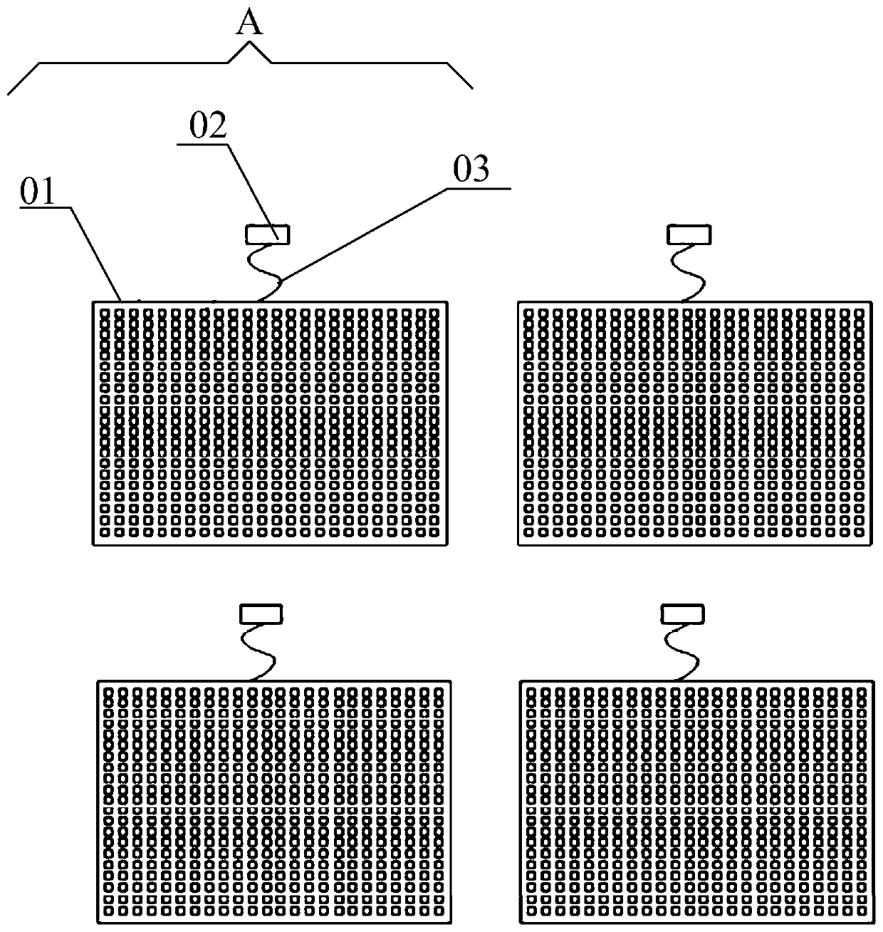
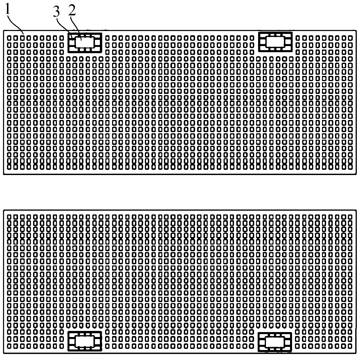
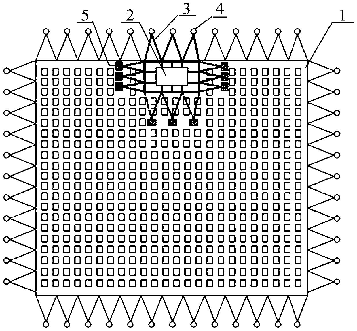
[0049] Please refer to figure 2The floating photovoltaic power station disclosed in the embodiment of the present invention includes a photovoltaic floating body array 1 and a floating platform 2. The photovoltaic floating body square array 1 is used to install photovoltaic modules to receive light energy and convert light energy into electrical energy. The platform 2 is used to install an inverter and booster device 6 to convert the electric energy generated by the photovoltaic module into an alternating current whose voltage and frequency meet the requirements. Compar...


PUM


Abstract

The invention relates to a floating type photovoltaic power station. The floating type photovoltaic power station comprises a photovoltaic floating body square matrix used for installing a photovoltaic module and a floating platform used for installing an inverter boosting device, wherein the floating platform is arranged in the photovoltaic floating body square matrix, the floating platform and the photovoltaic floating body square matrix are correspondingly and independently arranged on the water bottom through mooring cables, or the floating platform and the photovoltaic floating body square matrix are connected to form a combination body through mooring cables, and the combined system is arranged on the water bottom. According to the floating type photovoltaic power station, the relative fixation between the floating platform and the photovoltaic floating body square matrix is guaranteed, and mutual collision between the floating platform and the photovoltaic floating body square matrix is avoided; and on the other hand, the distance between two adjacent photovoltaic floating body matrixes in the same water area can be effectively reduced, so that the water utilization rate iseffectively improved.

Description

technical field [0001] The invention relates to the technical field of photovoltaic power generation on water, in particular to a floating photovoltaic power station and a method for adjusting the position of a floating platform and a square array of photovoltaic floating bodies. Background technique [0002] Currently mature floating photovoltaic power plants such as figure 1 As shown in , each floating photovoltaic power station includes a photovoltaic floating body square array 01 and a floating platform 02 corresponding to the photovoltaic floating body square array 01. The floating platform 02 is used to install inverter boosting equipment. The generated current flows into the inverter and booster equipment to realize inverter and boost. [0003] from figure 1 It can be seen from the figure that the floating platform 02 is arranged on the outside of the photovoltaic floating body array 01, and the two are independently moored. The inverter and booster equipment on the...

Claims


Application Information

Patent Timeline
Patent Type & Authority Applications(China)
IPC IPC(8): B63B35/44B63B21/50
CPCB63B35/44B63B21/50B63B2035/4453
Inventor 杨秋霞李二斌邹绍琨宋金鹏
Owner HEFEI SUNGROW RENEWABLE ENERGY SCI & TECH CO LTD
Why Eureka
Try Eureka